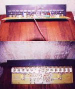
As you can see for the pic I have completed my first attempt at building the 500w amp that HugoBross posted a while back.
On testing of this amp with decreased supply rails (+-50v) and running it at about 200watts into a 7.5Ohm dummy loadI noticed the predrivers were running very hot (almost to hot to touch).<br>
So my question to you all is: is this just because my tiny heatsinks are way to inadequate or is this the symptom of a fault
An externally hosted image should be here but it was not working when we last tested it.
HOT DOG!!!!
OK, I suppose you are refering to Q6, 7. Yes, they get fairly warm but shouldn't be burning your finger. I'd guess 35C You can always use taller heatsinks. If you used different transistors, this may be an issue. Look for oscillation. I had that problem and couldn't set the bias. I built my amps from the Silicon Chip Magazine article and upon seeing your picture, I figured that you didn't have that information as your diff. pair and Q4, 5 weren't thermally bonded. In the article they say to do that so they will balance themselves and share current equally. My boards came from RCS Radio in Australia. They are the original design from the magazine article. OK, bias.... I don't know how you did yours but the article says to put a 390 Ohm 5W resistor in place of the fuses and measure DC volts across one. You will have proper biasing when the voltage across it reads 30 Volts. This gives, I think, 17mA across each device for a total of 77mA of bias current. I hopt these numbers are right. The 30V is right though. As you see, from my pictures, my bias transistor is above an output device instead of the middle, like yours. They say that it is a more accurate temp. measurement of the outputs as it is closer to them. The oscillation problem was solved when I added a 220pF cap across the 100pF cap going from collector of Q8 to base of Q7. I was then able to properly set my bias. Emitter resistors.... I use 5W ones just as the design says and I have ran mine at around 400W continuous for a while, and they only got warm, maybe 100 deg. F. I placed mine on the bottom of the board to save space. I also see that you don't use the .1uF caps along the rails on both sides. Looking at my boards, they did. I don't know if it really makes a difference though. I just tried to follow their design. On the output capacitor, they later said to use a 630V cap as at high frequencies and high power, it would fail in a very bad way. I suppose shorting the output. Thermally bonding the diff. pair also Q4 and 5....... press the flat sides together, with heatsink compound between them. Make sure they are still together after soldering. They get warm too, warmer than I have ever felt on any amp. They seem to get up to temperature and that's it, they don't get any hotter even at high power.
You will either need a bigger heatsink or a fan capable of a hurricane.") It takes a lot to cool "1.21 jigg-a-watts" unless you have a more efficient H.S. as mine, or even larger.
It takes a lot to cool "1.21 jigg-a-watts" unless you have a more efficient H.S. as mine, or even larger.
If you did your own boards, great job! May I encourage you to re-layout the board so you can thermally bond those parts and also add 4 outputs per rail. This will allow you to expand later if you wish, plus go into 2 Ohm loads with no problems!!!! A 90V rail will get you close to the 800W into 4 Ohms region!!! I did a very short 2 Ohm test on mine and with 58 Volts at max power, I got around 600W!!! With rails drooping to 58V, and 4 ohms, I got 413W into 4 Ohms. With 80V rails and droop at 68V, I'd easily get 500W. I'm using Peavey transformers from PV-.85K amps. I'd rather have one from a PV 1.3K amp though.... 90V rails!!!!! Oh well.............
Hope this helps. Sorry it was so long winded.
Chris
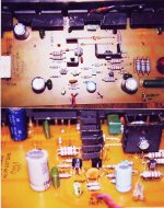
OK, I suppose you are refering to Q6, 7. Yes, they get fairly warm but shouldn't be burning your finger. I'd guess 35C
You can always use taller heatsinks. If you used different transistors, this may be an issue. Look for oscillation. I had that problem and couldn't set the bias. I built my amps from the Silicon Chip Magazine article and upon seeing your picture, I figured that you didn't have that information as your diff. pair and Q4, 5 weren't thermally bonded. In the article they say to do that so they will balance themselves and share current equally. My boards came from RCS Radio in Australia. They are the original design from the magazine article. OK, bias.... I don't know how you did yours but the article says to put a 390 Ohm 5W resistor in place of the fuses and measure DC volts across one. You will have proper biasing when the voltage across it reads 30 Volts. This gives, I think, 17mA across each device for a total of 77mA of bias current. I hopt these numbers are right. The 30V is right though. As you see, from my pictures, my bias transistor is above an output device instead of the middle, like yours. They say that it is a more accurate temp. measurement of the outputs as it is closer to them. The oscillation problem was solved when I added a 220pF cap across the 100pF cap going from collector of Q8 to base of Q7. I was then able to properly set my bias. Emitter resistors.... I use 5W ones just as the design says and I have ran mine at around 400W continuous for a while, and they only got warm, maybe 100 deg. F. I placed mine on the bottom of the board to save space. I also see that you don't use the .1uF caps along the rails on both sides. Looking at my boards, they did. I don't know if it really makes a difference though. I just tried to follow their design. On the output capacitor, they later said to use a 630V cap as at high frequencies and high power, it would fail in a very bad way. I suppose shorting the output. Thermally bonding the diff. pair also Q4 and 5....... press the flat sides together, with heatsink compound between them. Make sure they are still together after soldering. They get warm too, warmer than I have ever felt on any amp. They seem to get up to temperature and that's it, they don't get any hotter even at high power. You will either need a bigger heatsink or a fan capable of a hurricane.
It takes a lot to cool "1.21 jigg-a-watts" unless you have a more efficient H.S. as mine, or even larger. If you did your own boards, great job! May I encourage you to re-layout the board so you can thermally bond those parts and also add 4 outputs per rail. This will allow you to expand later if you wish, plus go into 2 Ohm loads with no problems!!!! A 90V rail will get you close to the 800W into 4 Ohms region!!! I did a very short 2 Ohm test on mine and with 58 Volts at max power, I got around 600W!!! With rails drooping to 58V, and 4 ohms, I got 413W into 4 Ohms. With 80V rails and droop at 68V, I'd easily get 500W. I'm using Peavey transformers from PV-.85K amps. I'd rather have one from a PV 1.3K amp though.... 90V rails!!!!! Oh well.............
Hope this helps. Sorry it was so long winded.
Chris
Attachments
ACD said:Those heatsinks are certainly to small.
If possible, I always put the predrivers on the main heatsink, or use heatsinks in the size of the main heatsink of a 25W amplifer.
Do as Sajti suggest
I never put the drivers on the main heatsink. The ouput devices heat the drivers, and this can results thermal runaway. My current amplifier has separated heatsink for the drivers, and predrivers. This heatsink is large, and keep the devices cold. Due the drivers run in class "A", the heat they generated is almost constant.
Sajti
Hi all,
I have bought same large TO220 heatsinks for this amp and will give them a go tomorrow, I will post the results.
The amp is not oscillating so once I have checked the new heatsinking I will put the amp on the final supply (1KVA 55-0-55 ACV) and set the Bias current.
Thanks for all the replies.
Matt.
Hey Jojo,
I can give it to you but it will not be to scale. Your best bet is to get the board from RCS Radio in Australia RCSRADIO@cia.com.au Part number SC01208971 500W amplifier You can e-mail Bob Barnes and he will take care of you. That's my suggestion. It cost me $50.00 US for 2 boards and shipping to USA. Not bad for that size of board and shipping from that far away.
Chris
PCB
Matth,
You have mail.
Diode,
I would appreciate it if you can send me whatever you have regarding the 500W amp pcb. Even if it is not to scale. Parts placement guide will be a big help too.
My email is ndijamco@edsamail.com.ph
Thanks,
JojoD
Matth,
You have mail.
Diode,
I would appreciate it if you can send me whatever you have regarding the 500W amp pcb. Even if it is not to scale. Parts placement guide will be a big help too.
My email is ndijamco@edsamail.com.ph
Thanks,
JojoD
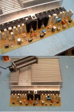
Here is the amp with the new pre-driver heatsinks (better me thinks! ) and the diff pairs thermally bonded as per Diodes instruction (cheers) you can also see that I have put the 390Ohm resistors in to set the bias (thanks again Diode).
What do you think of the main heatsink, i think it should be big enough. I have one per board and there is also a ducted fan that fits into the cutout which puts out loads of air with virtually no noise.
I will try to get it hooked up to the main supply and post final results.
Thanks for all the feedback.
) and the diff pairs thermally bonded as per Diodes instruction (cheers) you can also see that I have put the 390Ohm resistors in to set the bias (thanks again Diode).What do you think of the main heatsink, i think it should be big enough
. I have one per board and there is also a ducted fan that fits into the cutout which puts out loads of air with virtually no noise.I will try to get it hooked up to the main supply and post final results.
Thanks for all the feedback.
Attachments
Squirrel cage fan..... Very nice..... You went way overboard with the heatsinks but you'll definately have no trouble now!!! I tend to over design too, but I have very few failures to boast........ Great looking amp! You'll love it!!!!! I love how quiet it is.... No hiss or hum!!!!!!! Glad to see that you did the thermal bonding thing. You'll probably not see any difference but maybe you will. It should be more stable according to theory. E N J O Y!!!!!!!!!!!!
Chris
Chris
Hi JojoD,
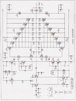
My board is 30cm in length, I don't think this helps you much as I did not use the Silicon Chip layout that you have. If you need to scale the jpg I would suggest using a TO3P transistor and lining it up with the holes in the layout, you can then scale the printout until it is right.
I would however suggest that if you are making your own boards that you use the traxmaker layout I sent you (this layout was from HugeBross, but I have modified the active componant part numbers to corespond with the parts list Diode has supplied) if you have trouble obtaining a copy of traxmaker PM me and I'll see what I can do.
Hope this helps.
Matt.
Hi matth,
did you use the pcb I've posted too or is this another one? I didn't make this amp yet, but I'm planning to.
Diode, I see you've scanned an article, do you have any further information of the article? you can send it to me at contact_FDC@hotmail.com
best regards,
HB.
did you use the pcb I've posted too or is this another one? I didn't make this amp yet, but I'm planning to.
Diode, I see you've scanned an article, do you have any further information of the article? you can send it to me at contact_FDC@hotmail.com
best regards,
HB.
- Status
- This old topic is closed. If you want to reopen this topic, contact a moderator using the "Report Post" button.
- Home
- Amplifiers
- Solid State
- Driver heatsink on 500w amp