For those of you modding the Master 7.
The grounding on the amp is not optimal: Mains protective earthing actually done at the IEC connector between mounting screw/chassis and IEC plug earth terminal through a ground loop breaker (2 x diodes and resistor).
This means that mains earth is not being connected directly to the chassis - possibly illegal in certain countries. And the chassis is actually signal ground, not good practise.
The ground loop breaker should be between signal ground and mains ground. This implies that the chassis is at signal ground - and the chassis is actually connected to signal ground of the PCBs at multiple points: mini XLR connectors, XLR connector, screw mounting hole closest to XLR connector is also actually signal ground (all other mounting holes on the output boards seem isolated from signal ground). I don't know about the DSP board as I've removed this.
The R-core transformer chassis and screen is earthed to the chassis via mounting screws on the transformer/rectifier PCB - these should be connected to mains earth directly for fault return, not signal ground (which is the chassis).
So to rectify the situation, I've basically connected mains earth directly to the chassis (which is connected to transformer/rectifier PCB ground) and isolated the output board signal grounds from the chassis so that it is not separate to mains earth. Typically you'd connect signal ground and mains ground together for situation where primary of transformer is shorted to secondary windings - given the physical arrangement of the R-core transformers, this situation is unlikely.
Oh and when you take apart the IEC connector shroud, marvel at its quality, and the shield around the mains cable through the centre floor of the DAC (sarcasm).
Also, with the Amanero USB module, just as Ian said, connection of PC to DAC introduces a significant amount of noise via USB GND (~double Vpk-pk noise). I highly recommend incorporating an Amanero isolator board from DIYINHK.
Reference reading re grounding: Earthing (Grounding) Your Hi-Fi - Tricks and Techniques
Hi,
I am in the long process (limited time for my hobby) of building my DIY DAC based on balanced 4xPCM1704.
I've nearly finished digital part of the project. Analog output is still in progress.
Lately I have connected I2S converter to my DAC.
I measured voltages on PCM signals and there are significant differences between them e.g.:
DRn = 2.72 V
DR = 0.62V
LLR = 0.1V
CLK = 0.66V
Is it OK?
Is DRn and DR should not be more or less equal?
Is LLR = 0.1V not too small?
Is my schematic (below) right?
An externally hosted image should be here but it was not working when we last tested it.
Guys,Hi,
I am in the long process (limited time for my hobby) of building my DIY DAC based on balanced 4xPCM1704.
I've nearly finished digital part of the project. Analog output is still in progress.
Lately I have connected I2S converter to my DAC.
I measured voltages on PCM signals and there are significant differences between them e.g.:
DRn = 2.72 V
DR = 0.62V
LLR = 0.1V
CLK = 0.66V
Is it OK?
Is DRn and DR should not be more or less equal?
Is LLR = 0.1V not too small?
Is my schematic (below) right?
An externally hosted image should be here but it was not working when we last tested it.
Do you have similar level of voltages on DRn , DR, LLR, CLK output?
I have:
DRn = 2.72 V
DR = 0.62V
LLR = 0.1V
CLK = 0.66V
Or maybe I have something broken in my I2S - PCM board?
Please confirm.
Last edited:
Guys,
Do you have similar level of voltages on DRn , DR, LLR, CLK output?
I have:
DRn = 2.72 V
DR = 0.62V
LLR = 0.1V
CLK = 0.66V
Or maybe I have something broken in my I2S - PCM board?
Please confirm.
Hi,
I'm not an expert, but i guess you can not compare active digital signal's by just use an meter. Also some digital outputs are floating if inactive, depending on chip and PCB design.
Regards
Marcus
What do you use for linking, the flat cable or uf-l ? Maybe a problem of contact on the LLR one, broken uf-l cable ?
I use UF.L connectors.
I've checked LLR connector and is OK. Right and Lefl LLR have the same level of voltages =0.1V.
I've measured frequency during playing 24/192kHz FLAC file.
Here is my results. Right and Lefl channel levels are nearly the same.
Below there is example of Right Channel:
An externally hosted image should be here but it was not working when we last tested it.
During playing 24/192 file I've measured also analog output of my PCM1704 with 100 Ohm I/V convert resistor and the output voltage is very low. I have +/-0,2 mili Volt [mV].
IS it right?
I just wanted to suggest to forget measuring voltages on these pins and try to measure frequency instead - several multimeters have this option.I've measured frequency during playing 24/192kHz FLAC file....
DL and DR frequencies does not matter here, you need a logic analyzer to see if the format is correct (which I suspect it is).
Are the jumpers set correctly for your DAC:
J24BIT - jumped
JHALF - open
JOB - open
JCONT - open
JTAIL - jumped
JLEAD - jumped
What frequency clocks are you using?
(I did not go back to your previous posts, you might have answered discussed these already)
I've set jumpers for full-speed mode:Are the jumpers set correctly for your DAC:
e.g J24BIT - jumped and JTAIL - jumped
22.5792 and 24.576 MHzWhat frequency clocks are you using?
Analog output voltage level (with resistor 100 ohm to GND) looks strange for me: Is very week (only +/-0,2mV).
Last edited:
JLEAD - should be left open (default), my bad on my previous post, but if JCONT is open (default) it will not affect the functionality anyway.I've set jumpers for full-speed mode:
e.g J24BIT - jumped and JTAIL - jumped
22.5792 and 24.576 MHz
Analog output voltage level (with resistor 100 ohm to GND) looks strange for me: Is very week (only +/-0,2mV).
What is the frequency on the u-fl that comes from the clock board?
The audio you are trying with is a continuous 0dB fix frequency, like 1KHz signal?
Dummy question but I sucked on this once: is volume turned to maximum on your source?
BTW. your schematic has a typo, the upper DAC is fed with DRn and its output is labeled as (+)... anyway, this is just a typo.
Last edited:
I2S frequency (for 24/192 content) are as follows:What is the frequency on the u-fl that comes from the clock board?
MCLK= 24.58 MHz
BCLK=12.288 MHz
LRCK=192kHz
DATA= about 2,8 MHz
Yes. I use Logitech Media Server (LMS) installed on my home network Linux server and Squeezelie as a player (BeagleBone Black +Debian).Dummy question but I sucked on this once: is volume turned to maximum on your source?
I've set "Output Level is fixed at 100%" in Volume Control parameter on my LMS.
Your readings seems to be correct, I presume you can read these frequencies at/close to your DAC pins too (somewhere on the DAC board).I2S frequency (for 24/192 content) are as follows...
- I presume if you stop/pause playing on the LMS, DATA line frequency will be 0.
- Can you confirm all voltages on the DAC board / at the DAC are correct.
- Did your DAC board work before with another PCM signal source, can you switch it to confirm its working? If no (new board) I would measure the negative side current draw of one or even both DACs, see figure 3 - datasheet page 8 of PCM1704.
YesYour readings seems to be correct, I presume you can read these frequencies at/close to your DAC pins too (somewhere on the DAC board).
I've checked. Yes- I presume if you stop/pause playing on the LMS, DATA line frequency will be 0.
-Vdd, +Vdd, -Vcc, +Vcc ranges from +/-4, 98 to +/-5,02V DCCan you confirm all voltages on the DAC board / at the DAC are correct.
Did your DAC board work before with another PCM signal source, can you switch it to confirm its working?
It is new my design (never worked with another PCM signal source). Schematic I enclosed in my previous posts.
Is it possible to measure negative side current draw without unsoldered PCM chip and without cutting existing tracks?If no (new board) I would measure the negative side current draw of one or even both DACs, see figure 3 - datasheet page 8 of PCM1704.
What voltage level should I expect from PCM1706 analog output playing loud music?
You don't need to unsolder nor to cut tracks, simply measure current on the negative wire that goes to your board.Is it possible to measure negative side current draw without unsoldered PCM chip and without cutting existing tracks?
You could play an 1KHz 0db test tone and measure that.What voltage level should I expect from PCM1706 analog output playing loud music?
Example for single ended output: your (+) I-out over 100R:
Output is +-1.2mA, 2.4mA Vpp with a 100R you should get 240mV Vpp that is 85mV RMS (you need a True-RMS Voltage meter). If your voltmeter is not True-RMS (but AC average rectified) you should see about 76mV.
Many thanks for the hint.You could play an 1KHz 0db test tone and measure that.
")
I've downloaded 1KHz mono WAVsample from:
Download Audio Tone Files
And tested with my source (BBB) and DAC.
Here are results without any I/U resistors:
An externally hosted image should be here but it was not working when we last tested it.
The results seem to be OK. What do you think?
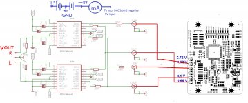
Your measurements are not correct.The results seem to be OK. What do you think?
The output I/U 100 Ohm resistor _must_ be there in order to have voltage output from your DAC.
You should measure mA on the negative rail that goes to your DAC -5V power supply.
See the ugly drawing I attached based on your schematics... its changed for stereo, L and R channels, if that is working you can modify it for balanced later.
See the output 100 Ohm resistors, you should measure ~ mV over there.
The mA meter should measure the negative power supply rail.
Attachments
Thank you very much vzx for your suggestions. I sent PM with more details.Your measurements are not correct.
The output I/U 100 Ohm resistor _must_ be there in order to have voltage output from your DAC.
You should measure mA on the negative rail that goes to your DAC -5V power supply.
See the ugly drawing I attached based on your schematics... its changed for stereo, L and R channels, if that is working you can modify it for balanced later.
See the output 100 Ohm resistors, you should measure ~ mV over there.
The mA meter should measure the negative power supply rail.
Hi,
I'm a bit of a latecomer to this thread, only just found it today !
Is it possible there is a PCB left to buy?
Thanks,
P.
Only one or two left
Good luck
Ian
- Home
- Source & Line
- Digital Line Level
- Drive NOS AD1865/62,PCM1704/02/63,TDA1541 from FIFO: Universal I2S-PCM driver board