I went with shielded cables for I/O to the phono section, and simple CAT5 twisted pair for all the control signals. Believe it or not, I haven't tested the phono section, but have no reason to believe it will not work as designed. I have a lovely JVC turntable I'm going to restore to its full luster as my first project when I get my shop back open. I may get some hum with the xfer so close, but I can shield that later if it's a problem. As it stands, all the other inputs were dead quiet the last time I listened to it.Hi Rick,
It's a good looking preamp. I'll stick with the silver knobs, but I have ordered some larger diameter ones to play with ;-)
You didn't give me your view on using screened or unscreened cable for the internal wiring... any thoughts?
Cheers,
Dave.
Rick
Thanks for the kind words Dennis. Long projects have to be a labor of love for sure. And it's extra tough when you're meticulous too! I try to plan out everything, but when it comes right down to it, DIY can sometimes be a design-as-you-go endeavor (usual is).Nice work Dave & Rick. Top notch work. I am enjoying this.
") You can't imagine just the number of hours I spent laying out the panels in Front Panel Express. But, in the end it was all worth it. Many times over. I feel this is one of the highest quality 'kit' I've built.
You can't imagine just the number of hours I spent laying out the panels in Front Panel Express. But, in the end it was all worth it. Many times over. I feel this is one of the highest quality 'kit' I've built.Dave has certainly raised the bar for all of us.
My version looks down right utilitarian, whereas his has got some real bling! His is just exceptional in every way. The more I build these projects, the more I learn about adding the extra touches that give it flair. My next big project is the discrete Honey Badger amp.Rick
I went with shielded cables for I/O to the phono section, and simple CAT5 twisted pair for all the control signals. Believe it or not, I haven't tested the phono section, but have no reason to believe it will not work as designed. I have a lovely JVC turntable I'm going to restore to its full luster as my first project when I get my shop back open. I may get some hum with the xfer so close, but I can shield that later if it's a problem. As it stands, all the other inputs were dead quiet the last time I listened to it.
Rick
Thanks Rick,
I was going to go for some Van Damme Pro Grade XKE 1 pair installation cable for the internal signal wiring, and just use flat cable for the relay switching signals. Or should I use screened cable for the relays too? I don't want any clicks to be heard
Thanks for kind words there and from Dennis tooDave has certainly raised the bar for all of us.
! But this kind of build doesn't happen quickly - I just had a look, and my first order was placed in December 2012. So it started out as a 2012 amp, and ended up a 2014 one! I ordered those red LEDs, but when they arrived they were yellow!
Turns out that one number different in the order code means a different colour - ha ha ha! I'm going to wire up the PSU this weekend and soon I should get the signal cable to wire for sound.....
Dave.
Flat or small twisted pair cable should work just fine for the control signal. You shouldn't hear any clicks coming through the audio. Yeah this project was longer than thought too. I think I started it in Spring of 2012 when the articles showed up in Elektor and finished it in late Fall 2012.Thanks Rick,
I was going to go for some Van Damme Pro Grade XKE 1 pair installation cable for the internal signal wiring, and just use flat cable for the relay switching signals. Or should I use screened cable for the relays too? I don't want any clicks to be heard
Thanks for kind words there and from Dennis too
I ordered those red LEDs, but when they arrived they were yellow!
I'm going to wire up the PSU this weekend and soon I should get the signal cable to wire for sound.....
Dave.
Rick
LEDs.... Arrrrrgh!
The SMD Red LEDs arrived... and didn't work! I just checked and they have the opposite polarity to the blue ones. When will they learn? Standardisation...?
Anyway, I had to cut some tracks on my illumination PCB and re-wire - now they're working. I'll post photos tonight (assuming my professional photographer (Wife) is available to shoot).
Dave.
The SMD Red LEDs arrived... and didn't work! I just checked and they have the opposite polarity to the blue ones
. When will they learn? Standardisation...?Anyway, I had to cut some tracks on my illumination PCB and re-wire - now they're working. I'll post photos tonight (assuming my professional photographer (Wife) is available to shoot
).Dave.
the special light conduits I designed for the pots (made by Schaeffer)
Any idea how these are manufactured ?
The SMD Red LEDs arrived... and didn't work! I just checked and they have the opposite polarity to the blue ones
Anyway, I had to cut some tracks on my illumination PCB and re-wire - now they're working. I'll post photos tonight (assuming my professional photographer (Wife) is available to shoot
Dave.
That's odd. I thought all LEDs followed the same standard. You red ones were different?
Attachments
SMD LEDs have standard markings, like this:
Was this not the case?
An externally hosted image should be here but it was not working when we last tested it.
Was this not the case?
That's odd. I thought all LEDs followed the same standard. You red ones were different?
SMD LEDs have standard markings, like this:
(Pic)
Was this not the case?
I'm using SOT-23 devices: Kingbright KM-23QBC-D (Blue) and KM-23SRD-F (Red) and they have opposite polarity. Also, from the beginning I had an issue with the blue ones - that diagram in the datasheet is from below the device, not above as I had thought
Never mind, I have them all working now... photos to follow...Max, I'm going to keep that pic for future use - I always struggle with those types too
Dave.
Any idea how these are manufactured ?
Yes, I designed them in Front Panel Designer and had them manufactured by Schaeffer (Front Panel Express in the USA/Canada). They needed a little filing to get them to fit though!
Dave.
Radio is Audio... right? (Sometimes?)
I also posted a little side project, if anyone hasn't seen it:
http://www.diyaudio.com/forums/everything-else/253164-elektor-general-coverage-1999-a.html
I didn't know where to post it. When my current Pre-Amp/Amplifier projects are done, I'll be continuing with it.
Dave.
I also posted a little side project, if anyone hasn't seen it:
http://www.diyaudio.com/forums/everything-else/253164-elektor-general-coverage-1999-a.html
I didn't know where to post it. When my current Pre-Amp/Amplifier projects are done, I'll be continuing with it.
Dave.
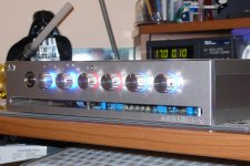
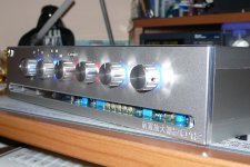
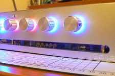
Excellent. The illuminated dials look a bit bright, but maybe that's just the photo. They can be exaggerated on computer screens. Otherwise it looks great. Maybe I missed it in the thread, but was the intent to show the components thru the acrylic legend strip? I guess there's lots of illumination inside the case as well with the dials, so it's kind of hard not to see them.Well, as promised here's the illuminated dials...
Those centre ones will go blue when Tone Defeat is switched off.
Dave.
Rick
Well, as promised here's the illuminated dials...
Those centre ones will go blue when Tone Defeat is switched off.
Dave.
I like this.Excellent. The illuminated dials look a bit bright, but maybe that's just the photo. They can be exaggerated on computer screens. Otherwise it looks great. Maybe I missed it in the thread, but was the intent to show the components thru the acrylic legend strip? I guess there's lots of illumination inside the case as well with the dials, so it's kind of hard not to see them.
Rick
The first 2 dials are a bit brighter because the rotary switch shafts are not cut down enough - I need to trim about another mm off of them. The photos were taken last night under energy-saving bulb conditions, so they are not a good view of what the dials really look like. Yes, the phono PCB is supposed to be visible through the legend strip and the top will also be transparent too. I will also be illuminating the interior and I have a fairly good plan with the feet - I'm hoping to give the impression that the amp is floating....
Keep watching this space...!
Dave.
Last edited:
It has a phono stage, tone control.
You imagine all that can be done easier and better with discrete parts ?
Bought in bulk, 5532/5534 opamps are dirt cheap.
If DIP8 sockets are used, all one has to do is a quick functionality check of the opamp, and plug it into the socket.
Placing 4 opamps in parallel adds some positions, doesn't make it more complex.
- Status
- This old topic is closed. If you want to reopen this topic, contact a moderator using the "Report Post" button.
- Home
- Source & Line
- Analog Line Level
- Douglas Self PreAmp 2012