Apparently these boards are still available direct from Elektor.
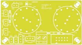
SET OF THE 6 PCB'S PREAMPLIFIER 2012 (110650)
Yes I know, but I only need PCB 110650-2, not all six of them.
Could a Preamplifier 2012 builder advise me about the Audio ground & Relay grounds?
In Elektor 06-2012, page 25 it says: -
"the audio ground and the relay ground must be connected together at one point only, right back at the power supply; othwerwise relay currents flowing in the audio ground will cause unpleasant clicking noises in the preamp output".
Thanks
In Elektor 06-2012, page 25 it says: -
"the audio ground and the relay ground must be connected together at one point only, right back at the power supply; othwerwise relay currents flowing in the audio ground will cause unpleasant clicking noises in the preamp output".
Thanks
Could a Preamplifier 2012 builder advise me about the Audio ground & Relay grounds?
As long as you provide your relay power & ground from the Power Supply "K4" to Front Panel "K6" your grounds are only tied at one point at the power supply.
I think the article is warning you should you deviate from this wiring scheme.
All you need to do is simply follow the wiring list I PM'd to you some time ago. I believe redjr also posted a similar wiring list in a much earlier post (#16).Could a Preamplifier 2012 builder advise me about the Audio ground & Relay grounds?
In Elektor 06-2012, page 25 it says: -
"the audio ground and the relay ground must be connected together at one point only, right back at the power supply; othwerwise relay currents flowing in the audio ground will cause unpleasant clicking noises in the preamp output".
Thanks
It's just a warning not to deviate from the published routing (as per their schematics for each board.
Geoff
Here we are in May 2018 with one Elektor Preamplifier still not working!
I'm trying to find the patience to get back to this build and try and get it to work!
Perhaps, i'll bin it completely and avoid future Elektor projects.............
OK. Let's take things in stages:
1. Have you got +/-17V at power pins of ICs on each PCB with active components (LLLL board, Phono board, main board)? Pin4 of all op-amps should be -17V, Pin 7 of NE5534 or pin 8 of NE5532 and LM4562 should be +17V.
2. Are all ICs in boards correct way round?
3. If you operate S5 (Input select switch), can you hear the input board relays clicking?
4. Are the correct interconnect leads going from each board to the correct place on whichever other board they are supposed to go to (check against the wiring list that redj and I posted /PM'd to you)?
5. On the Input board, have you connected jumpers onto JP1 - JP4 and onto S1 - S4? The way you do this should depend on what inputs you are intending to use (RCA or XLR, XLR as balanced or unbalanced inputs) - read Doug Self's text about the input board for info.
Last edited:
Do persevere, the amp is well worth it.
To help with providing appropriate advice, could you let us know what test gear you may have e.g multi-meter, oscilloscope, signal generator.
The prime problem I had when testing my build was that I hadn't set the jumpers correctly on the input board. This meant that my input signal wasn't actually getting as far as the phono and main board! Once the jumpers were set correctly, all worked exactly as expected.
Geoff
Gave myself a kick up the **** and got down to it!
Hopefully, some experts can give me some advise.
I have a DVD player, using an audio CD, the audio out is connected to the Left i/p pcb.
Power Supply is up and running. The -17v & +17 lines are ok.
The PSU is only connected to the LLL pcb, the Line/Tone/Vol pcb and Front Panel pcb.
The pcb's that are wired are the LLL, Line/Tone/Vol, Front Panel pcb and Left Input pcb.
The Left O/P is fine on the left Input pcb.
--------------------------------------------------------
I then connect K17 from the Left I/P pcb so that it also connects to K17 on the R/H pcb.
I also connected K15 from the I/P pcb to K1 on the Line/Tone/Vol pcb.
And then K16 from the I/P pcb to K3 on the Line/Tone/Vol pcb.
Result? No audio O/P on the R/H O/P of the Input pcb.
I thought i'd be clever so i then connected the L/Hand i/p signal from the Input pcb to the R/H input of the Line/Tone/Vol pcb, and then connected the o/p from the Line/Tone/Vol pcb to the Input.
Audio o/p was fine, proving that the Line/Tone/Vol pcb was working fine.
Any ideas why the R/Hand signal is not working?
Thanks
Last edited:
Connections done: -
K15 L/H i/p pcb to K1 Line/Tone/Vol pcb
K16 L/H i/p pcb to K3 Line/Tone/Vol pcb
R/H i/p pcb: -
K15 L/H i/p pcb to K2 Line/Tone/Vol pcb
K16 L/H i/p pcb to K4 Line/Tone/Vol pcb
Checking with my old scope: -
L/H i/p - K15 there is a signal on Line +, however on the R/H i/p on K15 Line + there is no signal!
Cheers
From what you have detailed in your last two postings, I think you are saying that both left and right channels of the main board (vol/tone/bal) are working - can you confirm this?
Also, can you confirm that the left channel is fully functional? If this is the case the problem lies with the right channel input PCB or the right channel interconnect wiring.
The Input pcbs have no active components on them and route one input connection to K15 on the input pcb. This particular input is selected by the switches within whichever relay is supplied dc power from the front panel rotary switch S5. Use your multi-meter (on one or other ohms range) to check the continuity of each signal path e.g. K1/K2 to K15 when source 1 is selected on the front panel switch. Do this check for Line+ and Line- and repeat for each source selection.
Last edited:
Preamp 2012 not working
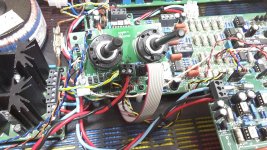
Hi Geoff, from what I did was to prove that the Line/Tone/Vol pcb was ok, feeding the left channel i/p through the right side, that appeared to be ok.
Those other checks ill do on Monday, so lets see.
Some images attached....
Thanks again.
Hi Geoff, from what I did was to prove that the Line/Tone/Vol pcb was ok, feeding the left channel i/p through the right side, that appeared to be ok.
Those other checks ill do on Monday, so lets see.
Some images attached....
Thanks again.
Attachments
Last edited:
Phono preamp
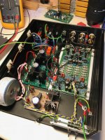
I'm building the phono preamp section of the Douglas Self preamp published by Elektor back in 2012. I got very intrigued by the design and wanted to give a test drive. My phono preamp is currently in a testing phase.
I did listen to it a bit and I can say that this phono preamp does sound very nice.
When I turn up the volume quite a bit there is a bit of noise and a bit of hum noticeable (when no music is playing). The preamp's gain is currently 60 dB in MC mode; I guess there is a price to pay with such gain settings. But I'm wondering if this could be improved by using the original 2SA1085 transistors (I'm using KSA992 transistors right now).
Has anyone else finished the preamp and tested the phone preamp (with an MC cart)? I would love to hear you comments.
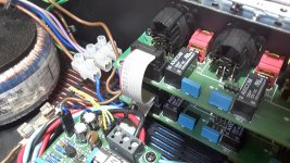
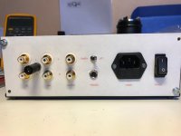
I have attached some pictures of my work in progress.
I'm building the phono preamp section of the Douglas Self preamp published by Elektor back in 2012. I got very intrigued by the design and wanted to give a test drive. My phono preamp is currently in a testing phase.
I did listen to it a bit and I can say that this phono preamp does sound very nice.
When I turn up the volume quite a bit there is a bit of noise and a bit of hum noticeable (when no music is playing). The preamp's gain is currently 60 dB in MC mode; I guess there is a price to pay with such gain settings. But I'm wondering if this could be improved by using the original 2SA1085 transistors (I'm using KSA992 transistors right now).
Has anyone else finished the preamp and tested the phone preamp (with an MC cart)? I would love to hear you comments.
I have attached some pictures of my work in progress.
Attachments
Last edited:
- Status
- This old topic is closed. If you want to reopen this topic, contact a moderator using the "Report Post" button.
- Home
- Source & Line
- Analogue Source
- Doug Self's New Preamp Construction and Pictures