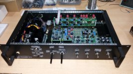
More.... Input PCBs with ribbon cable and some custom 2-pin interconnects.
Redjr, may i ask about the ribbon cable and connectors you have used?
Ideally, i would like to have a similar set up as yours with the Left & Right input pcb's, one above the other.
What connectors and cable have you used to connect the two K17 sockets together?
This cable then connects to K1 on the Front Panel pcb.
Thanks
I can't see how this preamp would outperform mine @ 110db CD / AUX signal / noise and virtually no op amp distortion. , plus tube warmth and musicality.
Would you like to share your schematics, please, best in a new thread?
Thanks in advance!
What is your source for the smaller 3/8" nuts used for the pots you mentioned??
Are these the 1W Dual 1K Pots? http://export.farnell.com/vishay/14920f0gjsx13102ka/potentiometer-1w-dual-1k/dp/8557314?ost=8557314&iscrfnonsku=false&ddkey=http%3Aen-EX%2FElement14_Export%2Fsearch
See the data sheet http://www.farnell.com/datasheets/439095.pdf
I am using the R.S. case 665-7719 | PF-19 Ventilated Rackmount Enclosure with Handles, 2U, 84 HP, 245mm Deep |
Might anyone having used this case have the Front Panel Designer files they used?
With thanks
Might anyone having used this case have the Front Panel Designer files they used?
With thanks
http://www.diyaudio.com/forums/chip-...ml#post5202416
If i'm to use the Front Panel Designer files from post 18, then based on muskyhuntr's post 6, i would like to ask about the following:-
Power On/Off switch used and order number?
Toggle Switches used for: -
Tone Defeat
MM / MC
IEC Amendment
Mains input socket (i need 240v) used and order number?
With thanks
I have finally been able to get back to this project build after so long.
Can anyone please give me any advise and steps that i should take and be aware of when doing the wiring?
Are there straight forward guides available of all the connections, including the d.c. connections?
With thanks
Calpe
Can anyone please give me any advise and steps that i should take and be aware of when doing the wiring?
Are there straight forward guides available of all the connections, including the d.c. connections?
With thanks
Calpe
I used Harwin connectors available through Mouser.
Headers & Wire Housings
Contacts to match
Use the Series Number M20 to find "number of positions"
And I bought this crimping tool on Amazon:
Engineer Inc PA-20 Precise Universal Wire Terminal Crimping Tool
You can get these connectors and crimper tools on eBay as well.
Headers & Wire Housings
Contacts to match
Use the Series Number M20 to find "number of positions"
And I bought this crimping tool on Amazon:
Engineer Inc PA-20 Precise Universal Wire Terminal Crimping Tool
You can get these connectors and crimper tools on eBay as well.
Cheers dennismiller55. I actually have variations of these : -
http://uk.farnell.com/harwin/m20-1180042/crimp-socket-gold-22-30awg-pk100/dp/1022219?ost=681-2878&iscrfnonsku=true&ddkey=http%3Aen-GB%2FElement14_United_Kingdom%2Fsearch
http://uk.farnell.com/harwin/m20-1060300/crimp-housing-3way/dp/865618?ost=681-2821&iscrfnonsku=true&ddkey=http%3Aen-GB%2FElement14_United_Kingdom%2Fsearch
I just wanted to be 100% sure how clear it is when connecting the pcb's together from all the connection points.
Thanks
Last edited:
Dennis plz see your P.M.
Just to mention to the late builders (like me) the NE5532's that were available when i purchased them were the NE5532AP.
http://uk.farnell.com/texas-instruments/ne5532ap/op-amp-dual-low-noise-5532-dip8/dp/1106091?ost=NE5532AP&ddkey=http%3Aen-GB%2FElement14_United_Kingdom%2Fsearch
You'll see here the supply voltage range is +5v - 15v.
The Elektor project has 17v supplies from the PSU.
In the above technical sheet for this i.c. it shows max. voltage is 22v, but recommended supply is 15v.
I wrote to Elektor explaining this and they told me to play it safe reduce R2 & R4 from 1.3k to 1.1k, which i have done, reducing the PSU o/p from 17 to 15v.
I'm playing it safe.
- Status
- This old topic is closed. If you want to reopen this topic, contact a moderator using the "Report Post" button.
- Home
- Source & Line
- Analogue Source
- Doug Self's New Preamp Construction and Pictures