You folks are shooting in the dark, a bit. Let me explain myself. First, let's only consider a class A amp on this thread. Second, learn about the devices that you are recommending, before putting them forward. For example, the MJ15003-4 combination has 1/2 the beta linearity and 1/2 the gain-bandwidth of my original 5884-5886 combination. There are MUCH better parts available today. The Hitachi K213-J76 series is flawed in a different way. You MUST cascode them to make them work reasonably well. The output conductance is completely dissimilar in the two devices. This leads to big-time 2'nd harmonic.
Some of the other circuit designs shown on this thread will work, but are not optimum, either to build or for other reasons. I hope that this helps.
Some of the other circuit designs shown on this thread will work, but are not optimum, either to build or for other reasons. I hope that this helps.
John,
what do you think about power limits in a true class A. Firstly lets speak about true class A (push-pull, not SE) without quiescent current change, dynamic current sources and other stuff like this. I am able to operate push-pull true class A to some 2 x 35W/8 Ohm when power input is about 2 x 80W at iddle. Each of the heatsinks (left and right) is about 0.2°C/W. Temperature of the heatsinks is about 55°C. Increasing iddle power input and thus power output tends to too high case temperature (I do not want to run them at some 70°C).
Now about dynamic current source (maybe not exact terminology) like Pass or d'Agostino. According to my experience and IMHO they degrade achievable sonic quality. That's why I am asking about max. reasonable output in a true push-pull class A.
Pavel
Hi Pavel , hi John,
I looked to some datasheets yesterday. I found that the Renesas 2SK2220/2SJ351 (available through Farnell) are very interesting devices. As written before I prefer the Toshiba 2SC5200/2SA1937 (yes they are the former 2SC3281/2SA1302) as output devices, easy to paralleling them and a cost effective solution. Paralleling 5 should be enough.
Driver? I'd reccommend the Toshiba 2SC5171/1930. And as input FETs the 2SK389/2SJ109.
There's only one thing missing: The bias stage. Will a Vbe multiplier work? I'm not shure because of the 2SK2220/2SJ351. Vgs(T) is different from Vbe(T) from a bipolar device. I've tested it with the HEXFETs, it works, but I don't know if it also does with the Renesas. Maybe we must use a more complex circuit to control the bias.

It's OK, Mark, I understand. I also used MJ15003's and 4's in a bridged 250W power amp that I designed for Gale in 1976. We started with the 5884-6's in the prototype, then we changed the parts to the MJ's. Well, the distortion doubled and the slew dropped in half. How would you know that? Today, we have LOT'S of parts that are better than either device in every way. We just have to find them, that's all.
Looking for high gain linear devices with the ft greater than 30 Mhz? Should they be run in parallel? 2sa1386a and 2sc3519a have good specs and sound good, but are hard to get. Have you looked at the specs for the new On-semi devices MLJ4281's that should be out soon? Who is Mark?
Looks like it was ")
I found data sheets for MJL4281A-MJL4302A
Hmmmm, looks interesting. I wonder when they are available for regular people to sample and play with?
mlloyd1
Oh, by the way, this is a great thread (thanks John for trying to keep it on topic)! Would I get in trouble by mentioning that the schematic for the ML2 is easily available on the web? It would be worthwhile to peruse in light of the discussion here.
I found data sheets for MJL4281A-MJL4302A
Hmmmm, looks interesting. I wonder when they are available for regular people to sample and play with?
mlloyd1
Oh, by the way, this is a great thread (thanks John for trying to keep it on topic)! Would I get in trouble by mentioning that the schematic for the ML2 is easily available on the web?
It would be worthwhile to peruse in light of the discussion here.john curl said:Must be a Freudian (sp) slip.


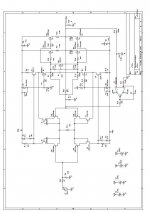
Yes, I would also replace R10 with a trim pot and run the front end off higher rails because of the gate to source drops of the mosfets.
I also notice that you have two feedback loops, any particular reason?
You might want to drop some resistance from the drains of M1 and M2 to ground to decrease your open loop gain.
Another experiment would be to leave the outputs outside the feedback loop.
Regards,
Jam
I also notice that you have two feedback loops, any particular reason?
You might want to drop some resistance from the drains of M1 and M2 to ground to decrease your open loop gain.
Another experiment would be to leave the outputs outside the feedback loop.
Regards,
Jam
Mr. Curl where are you?
How about this?
http://perso.wanadoo.fr/jm.plantefeve/nrds2.jpg
Regards,
Jam
How about this?
http://perso.wanadoo.fr/jm.plantefeve/nrds2.jpg
Regards,
Jam
Not Mr. Curl but....
Hi,
Geeeezzzzzzzzz, Jam....How come you know all this good stuff?
Cheers,
P.S. That amp runs in Class AB as it is shown.
Hi,
How about this?
Geeeezzzzzzzzz, Jam....How come you know all this good stuff?
Cheers,
P.S. That amp runs in Class AB as it is shown.


- Status
- This old topic is closed. If you want to reopen this topic, contact a moderator using the "Report Post" button.
- Home
- Amplifiers
- Solid State
- Does Anyone Here Like Class A amps?