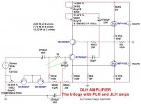
Congradulate Diego for the great design and others for the contribution. This is definitely 1 amp that we DIYers should build and have an audition. Just 1 input, the Pot that adjust SE/PP should be one that can carry high current as requested by Nelson Pass in PLH. The bootstrap C bring a high AC current thru this pot. And in this particular design, the bias POT also conduct this AC portion so need to be a higher watt rating one.
I am using standard 0.5w blue plastic multi-turn trimmers without issue. This is actually something you can replace with hard-set resistors once you adjust and like the bias setting and the harmonic profile.
I finally read Nelson Pass' article on the PLH - a great read and very informative. On the PLH, he does indeed recommend rather high wattage values for the bias pot P2 and R4.
Excerpted from the Pass DIY article for convenience:
I finally read Nelson Pass' article on the PLH - a great read and very informative. On the PLH, he does indeed recommend rather high wattage values for the bias pot P2 and R4.
Excerpted from the Pass DIY article for convenience:
Attachments
Last edited:
Of course
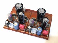
Here is the last version, the real size is close to the X design about 1Cm longer and there is a single jumper. I replaced the SMD type parts with hole true type. You can make your PC board longer to sandwich the power mosfets, I prefer them out of open for better cooling")
Here is the last version, the real size is close to the X design about 1Cm longer and there is a single jumper. I replaced the SMD type parts with hole true type. You can make your PC board longer to sandwich the power mosfets, I prefer them out of open for better cooling
Attachments
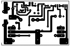
I put some color coding on it to make your life easier
Red = Semis
Yellow = Trimmers
Green = Resistors
Blue = Capacitors
Grey = Jumper
The size of the layout need to be scaled down at the print out
For the actual size please ask X, I did not printed out these yet (just finished the layout modification yesterday) + ad about 1Cm to the length
Soon I will print it out and let you know the correct size if you can wait for that
Attachments
Of course it would change bias settings, I only use Lateral MOSFETs in all my amps, for some reason I like them.
Edit: You will have to play with the bias settings a bit
Thanks Nico!
sp
I am using standard 0.5w blue plastic multi-turn trimmers without issue. This is actually something you can replace with hard-set resistors once you adjust and like the bias setting and the harmonic profile. <snip>
I think it take some time for the Pot to fail thru over current. Your suggestion to use fixed resistors after tuning was the option I picked in building my PLH. Of course you lost the option to do real time tuning afterwards.
Viewing the PLH amplifier circuit: R4, R6, P1 and P2 dissipate between 31.7% and 37.1% higher than the power dissipation of the trimpots marked as 2K5 and 500 ohms of the DLH.
This is due to the voltage supply voltage ratio and the Vgs tolerance: 20 V to 15.67 V.
The total nominal dissipation between the trimpots marked as 2K5 and 500 ohms, on the DLH amplifier, would be about 135 mW approx.
As for those who have requested a higher power option of the DLH amplifier, I must say that the most recommended way would be to provide an additional pair of MOSFET transistors to the scheme of post 1 (it becomes mandatory to use the gates stoppers). In bridge mode (two identical circuits per channel) we could achieve with extremely low distortion and pure class A, power up to 62 W over 2 ohms, or 31 W over 4 ohms, or 15.5 W over 8 ohms. That power would be per channel. The bias would be 4 A per channel. Exiting class A, it could deliver up to about 90 W over 2 ohms, with a distortion of 1% at 1 KHz approx.
regards
I still want to press on this, DLH is such an elegant design that I think we should minimize any reliability risk.
Looking into your comparison with PLH on dissipation, and your figure of 135mW, I believe your calculation is only based on idle status. You mentioned that the bias of the front end is 12.5mA, so I believe you use this as base and estimate the effective resistance between the 2 wipers of the 2 Pots. This comes close to 135mW? In such case, this is only as good as the amp is at idle. When it plays music, the 4700uF bootstrap capacitor will have an AC current flowing thru. This AC current will then flow thru the effective resistance between the 2 wipers of the Pots and then to +V, which is effectively GND in AC terms. I believe this AC current will be significant bigger than 12.5mA. I do not know how to calculate, but if you can help to check if you can read the current thru the 4700uF from your LTSpice model, say at 1W/8 Ohm output level. If we check that and still find the dissipation is OK, then I feel good. My guess is that it will not.
Looking into your comparison with PLH on dissipation, and your figure of 135mW, I believe your calculation is only based on idle status. You mentioned that the bias of the front end is 12.5mA, so I believe you use this as base and estimate the effective resistance between the 2 wipers of the 2 Pots. This comes close to 135mW? In such case, this is only as good as the amp is at idle. When it plays music, the 4700uF bootstrap capacitor will have an AC current flowing thru. This AC current will then flow thru the effective resistance between the 2 wipers of the Pots and then to +V, which is effectively GND in AC terms. I believe this AC current will be significant bigger than 12.5mA. I do not know how to calculate, but if you can help to check if you can read the current thru the 4700uF from your LTSpice model, say at 1W/8 Ohm output level. If we check that and still find the dissipation is OK, then I feel good. My guess is that it will not.
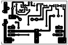
I did removed the jumper these last layout, I like to keep it simple
Thanks for the revised layout Gaborbela. In using mine, I am seeing RF pickup with cables being near my laptop. This amp has high bandwidth and probably should have something like 1k resistor on the input (after C1 and before Base of PNP) and 680pF film cap to ground to quiet the stray RF pickup.
Last edited:
Yes, Gaborbela, that is how its best done. You have to stop RFI getting into the amp, so a low pass filter has to be put at the very first stage.
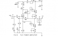
The RFI issue with this amp reflects the huge speed of the input stage. A Rush cascade is an emitter follower transistor out front of a grounded base transistor, T1 and T2, and both combinations are incredibly speed, so much that both are used in radar and UHF work. The output devices, the mosfets, are also very fast, so some care with layout and RFI ingress is needed on this amp.
You guys did a marvellous pcb!
Hugh
OK the RFI filter was added to the layout, these is the final version.
I printed out the layout I set up my printer at 50% or try to aim 76x113 MM.
Thank you for the amplifier circuit, to X the layout what I was able to modified, to AKSA for the help, encouragement, and finally thanks to all who showed any interest.
Now is time to order some parts and build it!
gabor
I printed out the layout I set up my printer at 50% or try to aim 76x113 MM.
Thank you for the amplifier circuit, to X the layout what I was able to modified, to AKSA for the help, encouragement, and finally thanks to all who showed any interest.
Now is time to order some parts and build it!
gabor
Attachments
- Home
- Amplifiers
- Solid State
- DLH Amplifier: The trilogy with PLH and JLH amps