Picodumbs is right about the output devices. You need a big heatsink for this amp and I wonder if taking the rails up to +/-24v and 1.5amp bias will be ok? Maybe Diegomj can answer. My reasoning is that I have several 24v rail Class A amp supplies for the typical Pass amp. A very useful SMPS configuration would be a pair of laptop 19v SMPS bricks for laptops in series. Add a mosfet cap multiplier and that will take it to 15v or 16v depending on cap Mx Vgs of mosfet. But it will make 4amps all day and not complain. The 4 cap Mx's will act as essentially independent PSU's and you get monoblocks with just a pair of SMPS bricks for better stereo separation. Main advantage I have found with SMPS Class A supplies is the almost total absence of any line mains peaks in the FFT - flat noise floor all the way to 10Hz. Of course, a decent SMPS brick is needed (like an HP, Dell, IBM, etc).
Another interesting mod to the DLH would be to make it single rail and cap coupled output. That gives automatic DC protect and no need to worry about DC offset adjustment. But more importantly, simplifies the the power supply by a lot. In this case, a single 19v to 24v SMPS brick capable of 4 to 5amps and two Juma Easy Peasy +ve rail cap Mx's can be used. The output swing would be a bit less but still quite a bit for many uses. Of course, a 5amp capable DC step up converter before the cap Mx to take it to 35v will give you 31v rails into the amp which will be equivalent in output swing. I do this all the time and it is my basic Class A power supply now.
Here is an example of the DC step up converter to get 35v from 19v (or even 12v).
New Arrival DC 3V 35V 0 10A Adjustable Digital Converter Step Up Boost Module USB 3 35V 60 x 52 x 22 mm Board-in Integrated Circuits from Electronic Components & Supplies on Aliexpress.com | Alibaba Group
Last edited:
I think these amplifier deserve a good quality PS.
Most Class A amplifier very (too) sensitive to the power supply, based on my experience that is the place where one can not save a few $$ because it will effect the end result. I built several Pass Clone,3 different Hiraga Class A, one Hiraga Le Monstre, one SEWA and some others, all of them where very sensitive to the power supply. It may measure (I am not sure) good but one must do A/B listening test mostly there you can realize how much influence has a good PS and VS a basic PS to the end result. Yes I have several 20-0-20VAC Plitron toroidal from the mentioned Clone amplifiers it would be great if I (we) could use them. I have at least 20Pc different type (V rating)of toroidals plus at least 8Pc other type of used transformers from dismantlement amplifiers at hand. I really think twice to buy more transformer - so many times I will rather pass on the project.
These is project very interesting would be great how X wrote if we could use Pass amplifier PS which usually 24-0-24V under class A load. I will wait to see where these project goes. I also have a 300VA 15-0-15VAC transformer right now with the ProFet clone may be I give a try with that. What I wanted to write saving on PS with a simple Class A amplifier it certainly lead us to reason if it worth to build or we just get a amp which produce some amplification.
The design premise was to avoid the greatest number of capacitors in the signal path and as part of the feedback network. The effects they cause there are known and demonstrable. The input capacitor cannot be avoided, since it allows the use of the amplifier in a universal way, unless we know the previous circuit.
Given this scenario, there are two options: Single power supply and Dual power supply. Which would we choose?
The answer was found by analyzing the need for very low noise in the absence of a signal. The elements that contribute to the own noise of the amplifier are those of the feedback network, among others.
In the single power supply option, the network resistors are exposed to a voltage of half of the power supply. If, on the other hand, we try to keep Johnson's noise as low as possible, we should set low resistance values for the network. This results in high power dissipations with little signal or even in the absence of signal. If the power sizing is not enough, we will have too much Johnson noise due to the temperature itself than to the resistance itself. This makes it not practicable or economical, to keep the noise level low. As the dissipation in the feedback network is not zero with little or no signal, there will always be an important contribution of noise, either by temperature or by minimum resistance values.
In the dual power supply option, things are very different. With little or no signal, the dissipation of the resistances of the feedback network is negligible. This allows to use relatively low values, with the consequent lower noise of Johnson and with the consequent smaller thermal jump over the one of environment. This maximizes the detail of the sound over the noise itself and help lowering the distortion. When there is a kind of high-signal pulse train, while instantaneous dissipation increases, and therefore temperature, the increasing noise is masked by the signal itself, which is several times higher in level. Masking helps us in this case") . Even it would not be unreasonable to use associations of various metal film resistors, so that each receives the lowest possible voltage. The maximum power oversizing is in accordance with keeping the lowest noise possible more than maximum signal excursion requirements.
. Even it would not be unreasonable to use associations of various metal film resistors, so that each receives the lowest possible voltage. The maximum power oversizing is in accordance with keeping the lowest noise possible more than maximum signal excursion requirements.
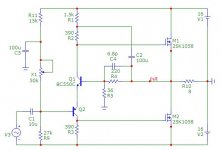
The current through the pair of input transistors was chosen at 12.5 mA, allowing them to be operated in their most linear zone of the hFE versus Ic curve. This current simultaneously allows to obtain optimal slew rates and high open loop gain.
There is a triple function for the pair of input transistors: as a differential amplifier to correct errors; as cascode, to favor a more extended and linear frequency response (in open loop); as a phase splitter, with greater gain symmetry compared to the unique transistor of Hood design. The Hood splitter bjt transistor suffers from a certain gain asymmetry towards both branches.
The current for the pair of output mosfets that best linearity offers is in the order of 2 A.
All these considerations make the DLH measure and sound as it does.
I do not think it's possible to push it far from its optimum point of design.
Best regards
Given this scenario, there are two options: Single power supply and Dual power supply. Which would we choose?
The answer was found by analyzing the need for very low noise in the absence of a signal. The elements that contribute to the own noise of the amplifier are those of the feedback network, among others.
In the single power supply option, the network resistors are exposed to a voltage of half of the power supply. If, on the other hand, we try to keep Johnson's noise as low as possible, we should set low resistance values for the network. This results in high power dissipations with little signal or even in the absence of signal. If the power sizing is not enough, we will have too much Johnson noise due to the temperature itself than to the resistance itself. This makes it not practicable or economical, to keep the noise level low. As the dissipation in the feedback network is not zero with little or no signal, there will always be an important contribution of noise, either by temperature or by minimum resistance values.
In the dual power supply option, things are very different. With little or no signal, the dissipation of the resistances of the feedback network is negligible. This allows to use relatively low values, with the consequent lower noise of Johnson and with the consequent smaller thermal jump over the one of environment. This maximizes the detail of the sound over the noise itself and help lowering the distortion. When there is a kind of high-signal pulse train, while instantaneous dissipation increases, and therefore temperature, the increasing noise is masked by the signal itself, which is several times higher in level. Masking helps us in this case
. Even it would not be unreasonable to use associations of various metal film resistors, so that each receives the lowest possible voltage. The maximum power oversizing is in accordance with keeping the lowest noise possible more than maximum signal excursion requirements.The current through the pair of input transistors was chosen at 12.5 mA, allowing them to be operated in their most linear zone of the hFE versus Ic curve. This current simultaneously allows to obtain optimal slew rates and high open loop gain.
There is a triple function for the pair of input transistors: as a differential amplifier to correct errors; as cascode, to favor a more extended and linear frequency response (in open loop); as a phase splitter, with greater gain symmetry compared to the unique transistor of Hood design. The Hood splitter bjt transistor suffers from a certain gain asymmetry towards both branches.
The current for the pair of output mosfets that best linearity offers is in the order of 2 A.
All these considerations make the DLH measure and sound as it does
.I do not think it's possible to push it far from its optimum point of design.
Best regards
Last edited:
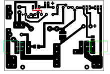
Note that my layout from post 93 has a couple of errors (in red). I will post an updated pdf later, or you can just draw in the fix yourself. Otherwise, the layout has been tested to work as shown below.

I am using just a single 0.22R 3W Panasonic resistor in place of the 0.15R 10W. It doesn't get that hot and the 3W works just fine.

![DLH-PCB-xrk-02].jpg](https://www.diyaudio.com/community/data/attachments/580/580537-9e98a1d9f296494599edfa293e16e5e9.jpg "DLH-PCB-xrk-02].jpg")

I am using just a single 0.22R 3W Panasonic resistor in place of the 0.15R 10W. It doesn't get that hot and the 3W works just fine.
Last edited:
The design premise was to avoid the greatest number of capacitors in the signal path and as part of the feedback network. The effects they cause there are known and demonstrable. The input capacitor cannot be avoided, since it allows the use of the amplifier in a universal way, unless we know the previous circuit. <snip>
Thanks for the detailed explanation between single and dual rail operation. I am playing with a variant in LTSpice with single rail and it performs very well in simulation for a headphone amplifier. I like cap coupling on the output for headphones for built in dc protection. One neat thing about this amp that reminds me of a Pass M2 in operation is the very slow ramp up of bias current. It starts at zero and slowly comes up over about 45 seconds before stabilizing. If you listen to it while this happens I think you hear the amp going through Class B, then AB, then pure Class A. Kind of neat but main benefit is no turn on/off pop. So a great feature for headphone use. I normally use a cap multiplier to slowly ramp current up in an amp, but here it is not needed.
Very interesting what you say about dual rail amps having lower Johnson noise for same bias current vs single rail. I am not sure I follow why still? Dissipation is the same in the resistors - all we did was change where 0v is referenced.
Last edited:
xrk971, you are the Amplifier champion builder. Which of the Class AB, Class A and Pass amps, can you company the sound of the DLH to? Or does it beat all of them hands down?
Thanks for the kind words Samuel but I think there are still many others who are better and faster amp builders. I am fast if the amp is simple (6 actives and under).
I have not hooked the DLH up to proper speakers in stereo yet so cannot say. Also, listening impressions should take a long term of weeks and lots of different material. I will need to pull the M2 out of its heat sinks and case and install the DLH as that is the only case I have capable of 60w/ch dissipation. I also need to see if +/-24v rails with a 400VA toroid will work or I may use two 19v SMPS bricks with cap Mx to drop to 15v rails. This will take several days as casework is the bane of speedy amp building.
You should try this amp though. Initial impressions with a headphone indicate that the sound is right up there among some of the best amps. Certainly a peer of my Pass amps. My favorite so far has been Ranchu/Aksa for Class AB and my Silicon Harmony for SE Class A.
Last edited:
Using Sharpie to trace PCB
Hi X,
Wondering if you can expand a bit on type of Sharpie pen(s) used. Was it one application only. Any indication of etching underneath the trace, etc.
I am asking because (1) I do not want to buy a laser printer and associated equipment for the TT method or UV or Laminate, (2) copper clad boards are easily available in Mexico. (3) I like to draw, and (4) seems to easy to send to a PCB house.
Thanks for the help,
Myles
Very interesting what you say about dual rail amps having lower Johnson noise for same bias current vs single rail. I am not sure I follow why still? Dissipation is the same in the resistors - all we did was change where 0v is referenced.
To understand what I explained, imagine two networks similar to the feedback network of this same amplifier. Each of the two networks will consist of two resistors of 100 ohms and 56 ohms, respectively. The maximum power specification of the resistors will be 2 W for the 100 ohm and 1 W for the 56 ohm, respectively.
With dual power supply, the network will receive peaks of up to + - 8 V, due to the output signal. In the absence of a signal, the network receives a negligible voltage.
With single power supply, the network will receive positive peaks of up to 23.67 V (ground reference) and negative peaks of up to 7.67 V (ground reference), due to the output signal. In addition, we will have on the network an average value of 15.67 V, due to the imposed condition of not having capacitors in the feedback network. In the absence of a signal, the network receives a voltage of 15.67 V.
It is evident that without signal applied, one network will develop heat, while the other network will not. While the temperature of one of the networks is similar to that of the environment, the other could be at a much higher temperature.
Although the resistances of both networks are similar both in value and physically, they are not exposed to the same operating temperature with or without signal.
I hope this helps to clarify everything.
Best regards
Last edited:
Hi X,
Wondering if you can expand a bit on type of Sharpie pen(s) used. Was it one application only. Any indication of etching underneath the trace, etc.
I am asking because (1) I do not want to buy a laser printer and associated equipment for the TT method or UV or Laminate, (2) copper clad boards are easily available in Mexico. (3) I like to draw, and (4) seems to easy to send to a PCB house.
Thanks for the help,
Myles
Hi Myles,
Only black color Sharpie works. I tried blue thinking it's all the same - it's not. Use it for 30 to 60 seconds at a time and replace cap to let it recharge otherwise it dries out. Color until you see no copper. Usually one layer and touch up bare spots. You can't really add second layer as fresh ink dissolves first layer and it's a mess. You can also use nail polish or even kids acrylic paint - it needs to be acid resistant for circa 5min to 20min depending on how strong your etchant is. I use muriatic (HCl) from hardware store aka "sidewalk cleaner" and drugstore hydrogen peroxide for cleaning wounds. About 1 part HCl and 2 parts peroxide. Use a small plastic spoon to stir acid solution constantly to have it etch evenly.
It's not as neat as laser printer transfer but sure is fun and fast. If you take care and use sharp razor to clean up Sharpie mask before etching it can look very neat. No undercut etching if timed properly. Don't leave in acid too long and stir solution constantly.
Last edited:
To understand what I explained, imagine two networks similar to the feedback network of this same amplifier. <snip>
Thanks for explaining this. I have LTSpice sims of dual rail and single rail amps and it's easy to check DC dissipation of resistors. I never noticed the single rail amps being hotter on feedback resistors - but makes sense since it sits at half-rail. Your amp has very low self noise indeed. With no music playing the output measures 0.0mV AC on my Fluke 101. Few speaker amps can claim that.
I wish someone would or will came up with a layout where the power mosfets placed like these for better heat dissipation. I hate fry wires, especially when the designer worked so hard to keep the component numbers low. I think with the original layout the two power mosfet is two close to each other, if someone has a rectangular shaped heatsink these layout would be much better. A la N Pass First Watt series. I used to draw layout with paint but I am just to busy with other project and that type of drawing required a lot of time. I see some nice layouts but neither is like these and of course it would be good for DIY community if iron transfer friendly (one sided) all the way DIY
Attachments
It's not at all too close together on my layout. It's that way because my existing heatsink holes are already drilled and tapped. If you have a thick base on your heatsink the current spacing of about 3in is plenty.
I like those long skinny "bar" shape Pass PCBs too but they are impractical to make at home and super expensive to order as costs rise exponentially with size. 100mm and under is the preferred size of you can manage it.
I like those long skinny "bar" shape Pass PCBs too but they are impractical to make at home and super expensive to order as costs rise exponentially with size. 100mm and under is the preferred size of you can manage it.
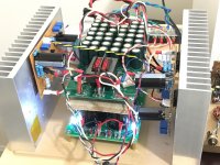
In Stereo finally. Just listening to headphones at present. Very nice SE Class A sound.
X,
Neat work.
Running at lower power for head phones or with the higher voltage power supply option you referred to earlier?
Wouldn't it be appropriate to place the thermal compensation transistors in close contact with the phase splitters? The amplifier has a DC gain of about 2,75 and with ca. 2mV/K VBE temperature coefficient the output could exhibit some unacceptable thermal drift. Especially if used with headphones.With no music playing the output measures 0.0mV AC on my Fluke 101.
I will be the pita to ask if it can be used with lateral mosfets.
Thanks, sp
Of course it would change bias settings, I only use Lateral MOSFETs in all my amps, for some reason I like them.
Edit: You will have to play with the bias settings a bit
Attachments
Last edited:
Wouldn't it be appropriate to place the thermal compensation transistors in close contact with the phase splitters? The amplifier has a DC gain of about 2,75 and with ca. 2mV/K VBE temperature coefficient the output could exhibit some unacceptable thermal drift. Especially if used with headphones.
Once warmed up the drift was only +/-25mV so not a problem but headphones was not my main use. Just testing for sound quality. Nothing beats a pair of high sensitivity headphones to ensure noise and hum are not a problem. Also, headphones don't have room effects so are more revealing of true sound signature of amp. For headphone use, I am making a single rail with cap coupled output. Much smaller and using all SMT.
- Home
- Amplifiers
- Solid State
- DLH Amplifier: The trilogy with PLH and JLH amps