Hi Diego,
DLH-Aleph would indeed sound very nice. You should make it.
Perhaps a DLH-M2 output stage would work well too. There are many alternatives to the usual 2SK170/2SJ74 front end on the various Pass output stages that can work well.
AKSA Lender Pass Hybrid M2 (ALPH-M2) Amp
DLH-Aleph would indeed sound very nice. You should make it.
Perhaps a DLH-M2 output stage would work well too. There are many alternatives to the usual 2SK170/2SJ74 front end on the various Pass output stages that can work well.
AKSA Lender Pass Hybrid M2 (ALPH-M2) Amp
Hi Diego,
DLH-Aleph would indeed sound very nice. You should make it.
Perhaps a DLH-M2 output stage would work well too. There are many alternatives to the usual 2SK170/2SJ74 front end on the various Pass output stages that can work well.
AKSA Lender Pass Hybrid M2 (ALPH-M2) Amp
Hi X,
I am carrying out the first simulations. The intention would be to be able to adjust the distribution of the distortion spectrum, achieve efficiency and be able to adjust the effect of the negative phase of H2 (to be able to adjust it in a wide range of amplitudes and frequencies of the signal).
We will see if everything can be achieved simultaneously.
You will not link the feedback resistor to +spk?
Excellent observation!!!. Happily, in my simulations the connections are as they should be
") , but the basic scheme that I have shown shows errors . Sorry about that.
, but the basic scheme that I have shown shows errors . Sorry about that.Anyway, I'm going to correct it so there are no doubts, just after polishing the latest results. I need some more time to be able to tame the beast.

Diego you are looking on wrong direction .
Very interesting is the modification that you have so cleverly proposed to the DLH. The need for an active element of low signal for the implementation of the dynamic current source Aleph is eliminated. The efficiency is increased and the profile and spectral distribution of the distortion is now attractive, with a predominance of H2 over H3 and successive ones (up to an input signal of 1.775 V RMS).
With a bias of around 215 mA, the THD is around 0.68%.
We can continue in that line, if you have suggested it and if you consider it necessary
.It will be possible to simultaneously achieve that the H2 phase remains negative over a wide range of amplitudes and frequencies of the input signal ?.
Attachments
Last edited:
Comparing the schemes of post # 1 and post # 527, it can be clearly deduced that:
The BC550C signal transistor is operating much further away from its maximum power dissipation limits in post # 1 than in post # 527. The ratio is approximately 3.76 times.
The variation of signal on the collector / base junction of the BC550C is much greater in the circuit of post # 527 than in the post # 1. The parasitic capacity present between those two electrodes takes more current in one situation compared to another. The ratio could be around 3.22 times. This could translate into marked limitations of high frequency reproduction. Remember i = C . dV / dt
When designing the DLH, these premises were taken into account, mainly the effect of collector-base junction parasitic capacity in both the BC550C and the BC560C. In the BC560C, its collector is almost locked to an almost constant voltage (or that varies very little in relation to a typical configuration in common emitter with resistive load in the collector), so that this connection significantly improves the high frequency reproduction.
The BC560C, while not connected as a cascode, behaves almost as if it were in that connection mode.
DLH post#1:
Vcb BC550C = 4.868 VDC
Vcb BC550C = 3.88 VCA
DLH post#527:
Vcb BC550C = 18.287 VDC
Vcb BC550C = 12.5 VCA
Last edited:
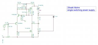
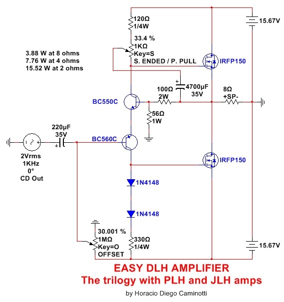
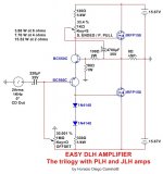
Very Simple and Easy DLH Amplifier
This version is one of the simplest versions to build. Although some elements have been eliminated, the performance can be equally as good as the versions already tested in bank.
A fairly simple and effective offset compensation has been implemented.
This version is one of the simplest versions to build. Although some elements have been eliminated, the performance can be equally as good as the versions already tested in bank.
A fairly simple and effective offset compensation has been implemented.
Attachments
Last edited:
Looks interresting
You could try this, just an idea
The diodes are for zero-out temp.compensation.
Mona
The 47uF cap is a mistake because it prevents the top FET from being pulled below zero Volts, ok below -vto, -4V. The feedback divider is also a required bias divider. The voltage at the bipolar BE junctions has to be high enough to turn on the lower FET but as low as possible to turn off the upper FET as much as possible, so it's a balance and a compromise.
You could add an offset between emitters so that the NPN emitter is below the PNP emitter. A similar circuit has a pair of NPNs as a diff amp operating under the FET vto voltage.
This version is one of the simplest versions to build. Although some elements have been eliminated, the performance can be equally as good as the versions already tested in bank.
A fairly simple and effective offset compensation has been implemented.

Hello!
I built this circuit (only deviation is IRF240 outputs), but I'm having problems with oscillations. If I short the input, it oscillates on a high frequency, I would guess MHz-range, since it is too high for my cheap oscilloscope. Oscillation amplitude is around 2Vpp.
With the input 'open' I only see some noise/hum pickup, so everything looks normal. Depending on what sound card I use, I see continuous or partial oscillation. The 'partial oscillation' is oscillation amplitude increasing on positive side of input sine, and decreasing on the negative. The continuous is another sound card, and that looks like a class D output signal.
I would guess the difference in oscillation between sound cards could be due to output impedance.
I also see it takes a long time to stabilize DC output and current through the amp. Big jumps in output DC when I disconnect/connect the input, and it takes a long time to stabilize (1 min -range).
I'm using a multi-turn trimmer for dc offset adjustment, but the adjustment is very sensitive.
It measures fine on distortion measurements, since the oscillation is on such a high frequency, so the sound card does not pick it up.
Anybody else built this last version. Ideas on what the cause is for oscillations? Have you seen this in other versions?
Confirmed! Thank you!
I started with a 'hum break resistor' and that helped a little bit (picked up noise from switched laptop supplies etc), but I saw oscillations on the positive peaks on higher levels, however, when I put the oscilloscope probe on the gate on the lower mosfet, the oscillations disappeared, so I knew I was on to something. Then I read your post, and the solution was confirmed! Playing music for the first time now (mono, only one channel built).
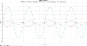
I did some THD and IMD measurements in 4 and 8 ohm that I will post later.
I started with a 'hum break resistor' and that helped a little bit (picked up noise from switched laptop supplies etc), but I saw oscillations on the positive peaks on higher levels, however, when I put the oscilloscope probe on the gate on the lower mosfet, the oscillations disappeared, so I knew I was on to something. Then I read your post, and the solution was confirmed!
Playing music for the first time now (mono, only one channel built).I did some THD and IMD measurements in 4 and 8 ohm that I will post later.
It is welcome that you are testing this latest and simple version .
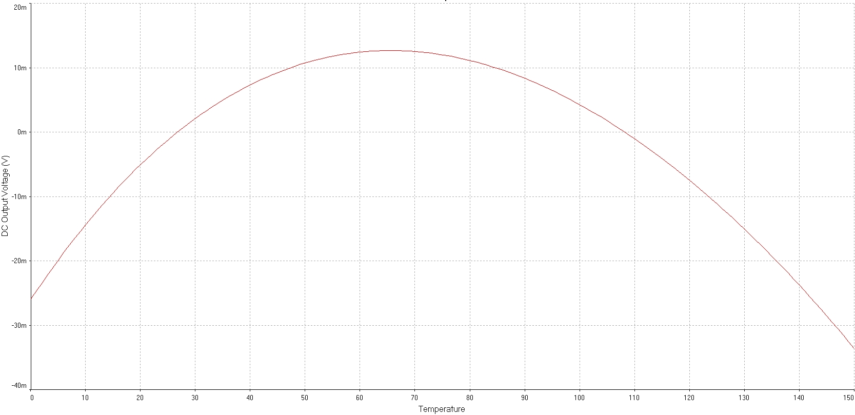
Have you been able to verify the shift in DC at the output with the temperature? The two diodes 1N4148 do their job?
What idle current have you measured? If this current is excessive (such as above 2 A), you can increase the resistor associated with the 1K trimpot. You would have to adjust the offset again.
I look forward to the results of distortion measurements.
Best regards
.Have you been able to verify the shift in DC at the output with the temperature? The two diodes 1N4148 do their job?
What idle current have you measured? If this current is excessive (such as above 2 A), you can increase the resistor associated with the 1K trimpot. You would have to adjust the offset again.
I look forward to the results of distortion measurements.
Best regards
- Home
- Amplifiers
- Solid State
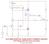
- DLH Amplifier: The trilogy with PLH and JLH amps