Has anyone tried this in multichannel mode ? I have installed drivers on both win7 and win10 and I get 6 visible channels of output in the driver/mixer (I'm using their latest driver, 3.38). I haven't connected it to my dac yet since there is an adator board to be made as well. Some form of reinsurance would be nice")
Hi,
Yes, with 8 channels@192 using DIYINHK multichannel DAC(other firmware). Works fine, but not DSD multichannel.
best,
Paal
This looks right.
Yes I thought so to
"Fluid" confirmed it another thread as well. "Fluid" said:
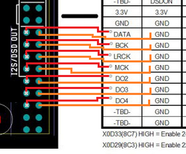
Yes that is right, matches the legend on the back of the board that I have.
I have only used it with macOS and that gave me 10 channel from memory, it
definitely had the full 8 channels that the ES9016 could use. I tested that.
I will be using this in a pc based (Win10) 3-way dsp/crossover with "Acourate" and
"J.River", followed by "Ackos" new 9038 multichannel dac. "Acko" is supplying
the multichannel dac's with the appropriate I2s adapter to the source it will
be connected to. Earlier the plan was to connect it to the "Najda" dsp I
already have but since that changed I will need a new adapter. That's why all
the questions, just making sure.
Spdif Coax to ttl converter (twisted pear) doesn't work
Hi everybody,
I know it's an old thread, but I hope one of you can help me.
About 2 years ago I bought the board and matching power supplies from diyinhk.com. Only now I came around to actually build the dac.
Everything works fine and the sound via USB is incredible, I am really happy.
But....
I also have a Sonos system and I want to connect it's spdif coax output to the spdif IN of my diyinhk ES9018 K2M.
I know (or I think?) I need to convert the consumer lever coax out of the Sonos Connect to a 3.3V (?) ttl level for it to work.
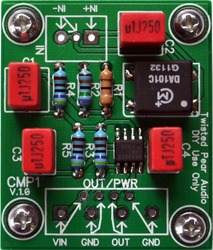
I bought this little "Single S/PDIF (or AES-EBU) Level Converter Kit" from Twisted Pear Audio (at bottom of page): The Buffalo III Digital-to-Analog Converter
The Problem: it doesn't work.... Meaning: there is no sound whatsoever. 
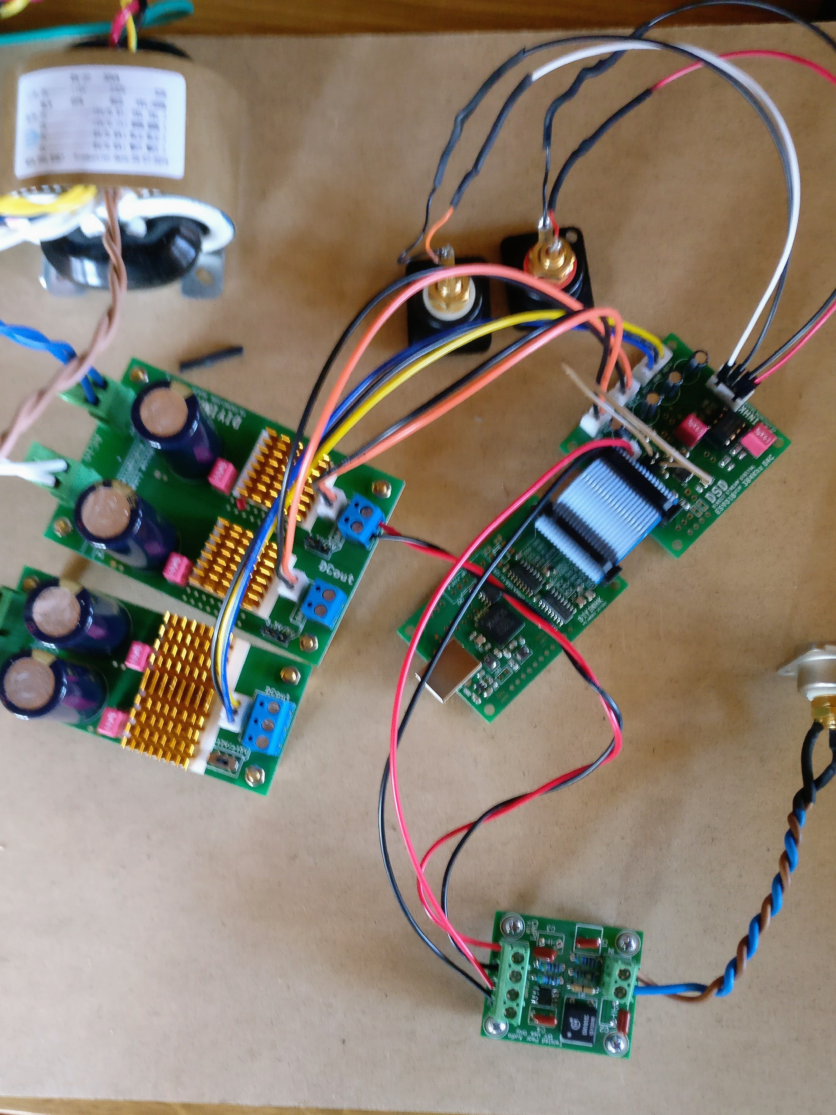
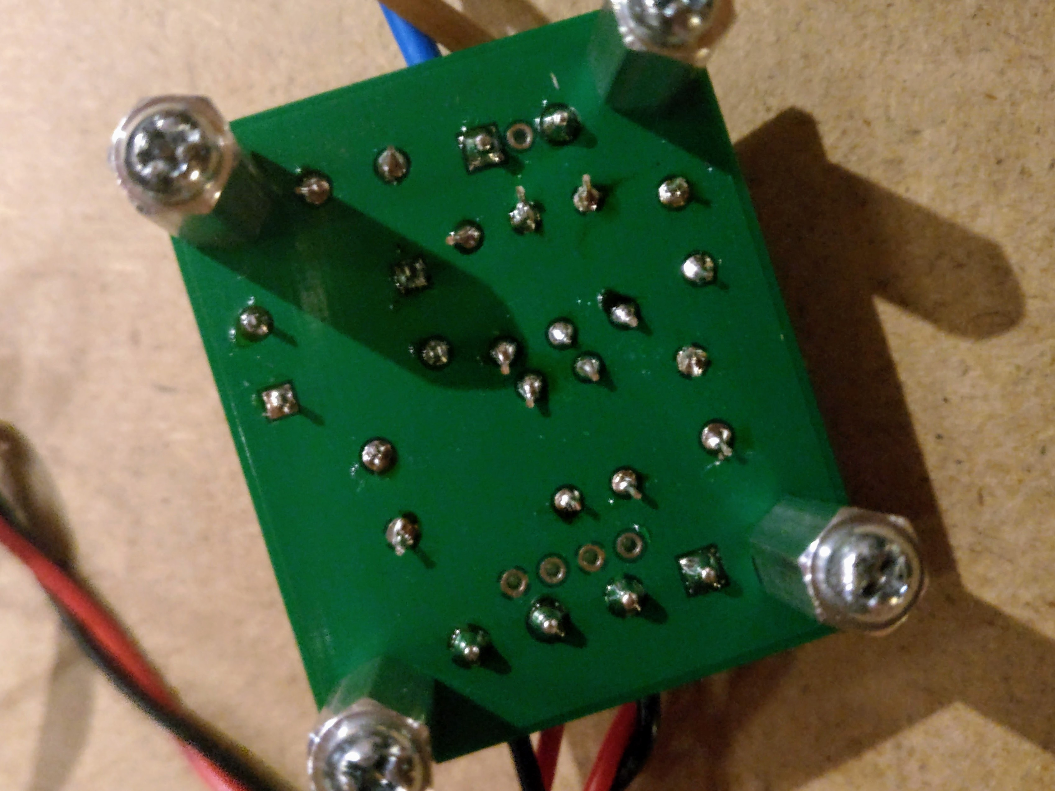
Here are some pics of my setup. Maybe someone can see a mistake I might have made (soldering, wiring...)?
I tried using the 3.3V from my dac's power supplies (digital 3.3V) as well as an externel power supply of 9V - to no avail.
Any tips/hints/help is much appreciated!
best regards
Stephan
Hi everybody,
I know it's an old thread, but I hope one of you can help me.
About 2 years ago I bought the board and matching power supplies from diyinhk.com. Only now I came around to actually build the dac.
Everything works fine and the sound via USB is incredible, I am really happy.
But....
I also have a Sonos system and I want to connect it's spdif coax output to the spdif IN of my diyinhk ES9018 K2M.
I know (or I think?) I need to convert the consumer lever coax out of the Sonos Connect to a 3.3V (?) ttl level for it to work.
I bought this little "Single S/PDIF (or AES-EBU) Level Converter Kit" from Twisted Pear Audio (at bottom of page): The Buffalo III Digital-to-Analog Converter
The Problem: it doesn't work....
Meaning: there is no sound whatsoever. Here are some pics of my setup. Maybe someone can see a mistake I might have made (soldering, wiring...)?
I tried using the 3.3V from my dac's power supplies (digital 3.3V) as well as an externel power supply of 9V - to no avail.
Any tips/hints/help is much appreciated!
best regards
Stephan
The schematic on the Twisted Pear site says 5V which is available from the Buffalo. If you have 5V available from the DIYINHK power supply try that.
Having given it 9V it is possible that you have damaged the IC but without knowing what chip it is hard to say.
It looks like you have connected to the spdif header and closed the spdif jumper but your picture is blurry. Take another one closer to the DAC board and I can tell you if you have it wired correctly.
Do you have a multimeter to measure if there is any voltage on the pins of the twisted pear board?
Thanks you for looking into this, fluid!
I checked everything and the DAC including the twisted pear board seem to meassure fine. But I cannot get any DMM-reading from the digital out of my Sonos Connect....!
Tried 2 different coax cables, will try another one and I will also try a different digital/coax source and feed it to the DAC. Never used the digital outs of the Sonos COnnect, so I cannot imagine why it should be broken, but...you never know.
Will report back. Again: thanks a lot, fluid!
Best regards
Stephan
Are you using 5V for the twisted pear board now?
Check the connections on how you have the SPDIF wired, try reversing the wires any see if that makes any difference. Make sure that the SPDIF jumper points are closed on the DAC board.
If the SONOS has optical out that works with the cheap optical input board from DIYINHK or twisted pear.
There is a schematic for a simple coax to TTL converter here at the bottom of the page
S/PDIF Digital to Analogue Converter
You could probably breadboard that.
There is no need to disconnect the USB i2s, the input is selected by a jumper in hardware or in software. If the spdif jumper is closed the DAC will use the spdif line and if it's open it will use the i2s.
If you use a software controller you can have both connected and switch between them.
Does no harm to disconnect but it would be very strange if that had any effect on your issue.
If you use a software controller you can have both connected and switch between them.
Does no harm to disconnect but it would be very strange if that had any effect on your issue.
@fluid: sorry for a dumb question: S/PDIF Digital to Analogue Converter --> doesn't it need a 5V input? I don't see it in the schematic.
Again: I know it probably is a dumb question....sorry.
I would like to breadboard it to try if I may have burnt my twisted pear converter.
Again: I know it probably is a dumb question....sorry.
I would like to breadboard it to try if I may have burnt my twisted pear converter.
Not a stupid question and yes it would. There is a schematic for a 7805 based one further up the page
Did you try your Twisted Pear board at 5V?
Worst case with the twisted pear board would be replacing the chip. Those 8 pin SMD chips are easier to damage through over heating or you could have got a bad one. The other components should have no issues with much larger voltages than 9V.
Did you try your Twisted Pear board at 5V?
Worst case with the twisted pear board would be replacing the chip. Those 8 pin SMD chips are easier to damage through over heating or you could have got a bad one. The other components should have no issues with much larger voltages than 9V.
If you use a 14 pin device like the SN74HC04N from TI then pin 14 is Vcc at 5V and pin 7 is ground.
The device above is in a dip package so you can use it in a socket or breadboard.
With those chips you need to tie the unused inputs to either Vcc or ground they can't be left floating. The datasheet has quite a lot of information in it.
The device above is in a dip package so you can use it in a socket or breadboard.
With those chips you need to tie the unused inputs to either Vcc or ground they can't be left floating. The datasheet has quite a lot of information in it.
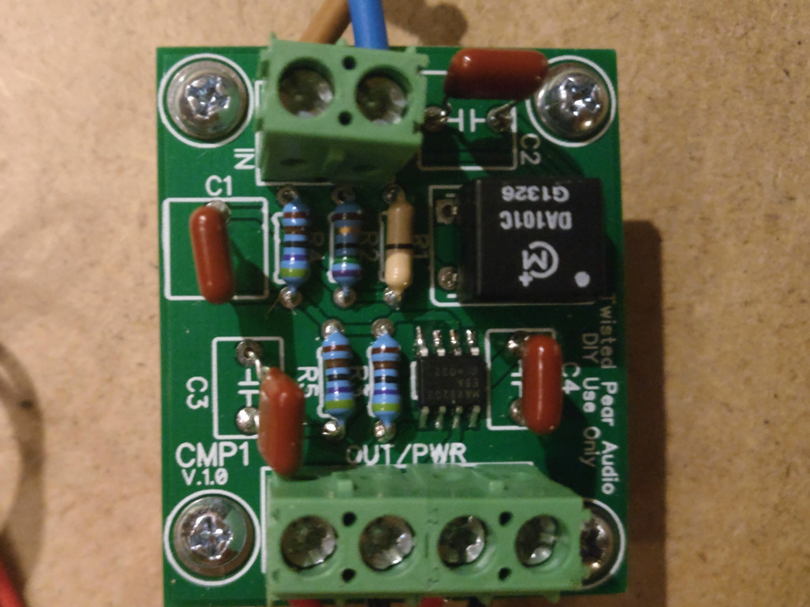
I think Twisted Pear are using the Maxim 9203 comparator. They use the 9201 quad comparator in the 4 channel board so it makes sense they would use the single version of that chip and it matches the schematic. I just checked your image and it does seem to say MAX9023 ESA on the chip which is the correct marking for the 8 pin chip.
Maximum Vdd for those chips is 7V so 9V may well have killed it. They are not expensive so you could try and replace it.
I found another page with some similar circuits to the ESP one but using slightly different hex inverters.
S/PDIF input - HwB
Maximum Vdd for those chips is 7V so 9V may well have killed it. They are not expensive so you could try and replace it.
I found another page with some similar circuits to the ESP one but using slightly different hex inverters.
S/PDIF input - HwB
I was looking for the little smd chip's description....
Yes, it says MAX9023 ESA but the possible replacements I have have a the same name but a slightly different number underneath. I think it describes some frequency rating or range? Do you think I should try anyway?
I also received the optical receiver from diyinhk today. Will try that as soon as I have bought an optical cable. Must have dumped all of them a long time ago.
And thanks again for all your help!
Last edited:
- Home
- Vendor's Bazaar
- diyinhk Store