It might be working to some extent but it certainly won't be working well if you are only giving power to the digital parts of the DAC.
I would wait until you can power the output circuit and both the digital and analogue parts as I can't see the reason for testing parts of it.
As long as you supply the correct voltages and solder the parts the right way this DAC will work and sound very good.
I would wait until you can power the output circuit and both the digital and analogue parts as I can't see the reason for testing parts of it.
As long as you supply the correct voltages and solder the parts the right way this DAC will work and sound very good.
I did power digital AND analog (and yes, it works, bad, with only digital supply).
It works well (with a condo) on the raw balanced input with a single ended amp. I did not know that balanced raw input would have a DC offset.
Maybe i will squeeze the output stage in final implementation. What would be the best between an AOP or a passive decoupling with condo ? Does i have other alternatives ?
With usb i have some some artefacts from grounds and noise on usb (i did not use my intona and ethernet isolation for this test) that i don't have with toslink.
I did hesitate with isolated version when i pass the order. Do you know what would be the added jitter generated by isolator ?
I saw the jipihorn test on ESN9018. the self master clocking + ASCR seam very jitter unsensible. So a good isolation in the case of ES9018 could be a greater benefit than the added jitter because of the isolation ...
Any feed backs ?
and ... I have unexpected pops when switching from a bitrate to another.
Bernard
Last edited:
I did power digital AND analog (and yes, it works, bad, with only digital supply).
It works well (with a condo) on the raw balanced input with a single ended amp. I did not know that balanced raw input would have a DC offset.
Every current output DAC that I have seen uses the same configuration and floats the differential output on half the AVCC voltage. In a differential circuit it is irrelevant but is a real problem if you only use one phase into a single ended input without a coupling capacitor.
Maybe i will squeeze the output stage in final implementation. What would be the best between an AOP or a passive decoupling with condo ? Does i have other alternatives ?
Have a look at this link as you will be using the DAC in voltage output mode
https://hifiduino.wordpress.com/2013/07/15/how-good-is-es9018-in-voltage-mode-part-ii/
A google search for ES9018 voltage mode will also turn up lots of information.
With usb i have some some artefacts from grounds and noise on usb (i did not use my intona and ethernet isolation for this test) that i don't have with toslink.
You are running this DAC without any output filter so all the ultrasonic rubbish is not being filtered away at all. You will need to use an RC filter to get rid of most of this. It is possible that this is what you are hearing. If you are getting a lot of ground hum and buzz and none with an optical connection then you have a ground loop issue.
I did hesitate with isolated version when i pass the order. Do you know what would be the added jitter generated by isolator ?
A lot of isolator chips will add around 100 picoseconds of jitter which is quite a lot, this is why they are almost always re-clocked after the isolator.
I saw the jipihorn test on ESN9018. the self master clocking + ASCR seam very jitter unsensible. So a good isolation in the case of ES9018 could be a greater benefit than the added jitter because of the isolation ...
I don't really understand what you mean here. The Sabre does a pretty good job of reducing jitter on the input and the diyinhk board has a good crystal so you could try using an isolation stage and let the DAC sort out the clocking. The benefits of isolation should be fairly subtle unless you are using it to combat a ground loop from the usb connection.
and ... I have unexpected pops when switching from a bitrate to another.
Bernard
That is probably due to the USB interface and the diyinhk board does not have a mute relay on board which is often used to solve that problem.
I did a test this morning with DSD in native format from squeezelite on etalon streamer. It works well with no pops.
It was a test suggested by diyinhk support so see if ES9018k2m hardware was working.
I does not.
With native DSD the volume control in Ipeng is inoperant.
Does someone make the hardware volume mode works with squeezelite on raspberry or SBT ?
Thank you
Bernard
It was a test suggested by diyinhk support so see if ES9018k2m hardware was working.
I does not.
With native DSD the volume control in Ipeng is inoperant.
Does someone make the hardware volume mode works with squeezelite on raspberry or SBT ?
Thank you
Bernard
Does someone make the hardware volume mode works with squeezelite on raspberry or SBT ?
The hardware volume control only works through i2c commands being passed to the dac through the SDA and SCL connectors.
This can be done with an outboard microprocessor like arduino or a custom xmos firmware. There needs to be a hardware connection to change the registers in the DAC there is no other way around it.
The DiyinHK kit with XMOS usb card does take the volume info from player through USB and pass it to ES9018k2m chip thought I2C (Diyinhk USB XMOS card has a special firmware for this).
It is supposed to work with system default sound control under linux, but i don't know if there are parameters to set in /etc/asound.conf for it to works with squeezelite.
It is supposed to work with system default sound control under linux, but i don't know if there are parameters to set in /etc/asound.conf for it to works with squeezelite.
I would think that the "system" volume control would not be the same as that used in a program and that you will need to manually move the main system volume slider in the control panel or set it via console input.
I have used a diyinhk xmos card with a mac and there are sliders in the control panel that you can use to control volume. I think you would have to trust that i2c commands are being sent to use the hardware volume in this way unless you have some way to monitor the i2c buss to confirm it.
I have used a diyinhk xmos card with a mac and there are sliders in the control panel that you can use to control volume. I think you would have to trust that i2c commands are being sent to use the hardware volume in this way unless you have some way to monitor the i2c buss to confirm it.
Hi, Yes
It works that way ; but it might be a way to bind the software control on system control in /etc/asound.conf ... but i don't know how and don't find feed back on this subject.
I asked to diyinhk, i am waiting for the reply...
That is really more of a linux software issue and I doubt you will get much of an answer from diyinhk....
You could control amixer from the command line to set the volume remotely
amixer
I use an arduino with modified hifiduino code and that lets me control the hardware volume and set all the filters with a rotary encoder and apple remote. It is a very good solution to controlling this DAC. The different filters on the k2m do have an audible effect on the output and IMO it is worth using the arduino for this alone.
Yes, i don't want to spend hours and day in linux code, and i will probably go for an arduino. Did you isolate i2c ? I have seen some cheap pcbs for this but i did not find what is the minimum bit rate for i2c to work with Es9018.
I took a look to the output stage today (i am waiting for my lifepo4 12v batteries). I see that there is no resistive load and no filter capacitor before the OPA. Isn't it supposed to have one ? Did you keep the original AOP ?
Thanks for your precious advices.
Bernard
I took a look to the output stage today (i am waiting for my lifepo4 12v batteries). I see that there is no resistive load and no filter capacitor before the OPA. Isn't it supposed to have one ? Did you keep the original AOP ?
Thanks for your precious advices.
Bernard
As yet I haven't isolated the i2c bus or the USB input. I have bought a couple of Adum1250 isolator and level converter chips to try. They are SOIC 8 and can just be used mounted to an SOIC 8 to DIP pcb board. Silicon labs makes isolator chips that work well to.
I am using the supplied output stage as it is very expensive to build or buy one that performs much better. The supplied one looks very similar to the single ended only version from the sabre evaluation board which has the RC filter after the op-amp.

This is only 2dB worse in THD which is still -112dB (Figure 3) for an ES9008 using the single op-amp if you use a good one like LME49720/LM4562. Comparison table shown below.

This is the thread I posted about the build of my k2m DAC
http://www.diyaudio.com/forums/digital-line-level/295919-es9018k2m-build-completed.html
http://www.diyaudio.com/forums/digital-line-level/295201-es9018k2m-arduino-ir-remote-issue.html
and this is a thread about an issue I had to get my apple remote working. I have posted the code that I have used in that thread and there is information on a simpler way to get the remote working at the end. I haven't tried that myself but I will soon as I have got the diyinhk ES9016 DAC in construction at the moment and modifying the hifiduino code to work with that is my next job.
I am using the supplied output stage as it is very expensive to build or buy one that performs much better. The supplied one looks very similar to the single ended only version from the sabre evaluation board which has the RC filter after the op-amp.
This is only 2dB worse in THD which is still -112dB (Figure 3) for an ES9008 using the single op-amp if you use a good one like LME49720/LM4562. Comparison table shown below.
This is the thread I posted about the build of my k2m DAC
http://www.diyaudio.com/forums/digital-line-level/295919-es9018k2m-build-completed.html
http://www.diyaudio.com/forums/digital-line-level/295201-es9018k2m-arduino-ir-remote-issue.html
and this is a thread about an issue I had to get my apple remote working. I have posted the code that I have used in that thread and there is information on a simpler way to get the remote working at the end. I haven't tried that myself but I will soon as I have got the diyinhk ES9016 DAC in construction at the moment and modifying the hifiduino code to work with that is my next job.
Hi all,
I have just been wading through the entire topic because I'm building one as well. I was wondering whether my assumption of just using the DAC board alone would work as an SPDIF-only DAC is correct. With the approprate power supplies and SPDIF to TTL converter of course.
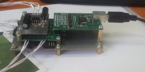
So at the moment I have a SPDIF to TTL converter connected to the DAC board with the ultra low noise power supplies also supplied by DIYINHK. Just waiting for the R-core transformer to fire the thing up.
I have just been wading through the entire topic because I'm building one as well. I was wondering whether my assumption of just using the DAC board alone would work as an SPDIF-only DAC is correct. With the approprate power supplies and SPDIF to TTL converter of course.
So at the moment I have a SPDIF to TTL converter connected to the DAC board with the ultra low noise power supplies also supplied by DIYINHK. Just waiting for the R-core transformer to fire the thing up.
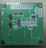
It says Data, Latch, Clxl and Clxr.
Shouldn't it be BitClock, LatchEnable, LeftData and RightData? Did clock and data labeling get mixed up?
I'm interested in buying the kit, but I'd like to see the schematics first, so that I know what exactly I'm buying.
I'm thinking of using the TDA1541A in simultaneous mode with the TDA1540 input signal hijacked from this kit.
Or maybe I should wait for you guys to come up with a similar kit with a TDA1541A in a simultaneous mode. If you do that, I'm buying immediately.
Hi all,
I have just been wading through the entire topic because I'm building one as well. I was wondering whether my assumption of just using the DAC board alone would work as an SPDIF-only DAC is correct. With the approprate power supplies and SPDIF to TTL converter of course.
So at the moment I have a SPDIF to TTL converter connected to the DAC board with the ultra low noise power supplies also supplied by DIYINHK. Just waiting for the R-core transformer to fire the thing up.
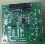
Yes the DAC will work fine with just TTL level SPDIF. You will need to short/jumper the SPDIF ON connectors which are just next to the SPDIF input unless you use a micro controller to select the SPDIF line.
Check that you have the SPDIF connections wired correctly otherwise you will get a weird clicking noise as an output if you get signal and ground the wrong way round.
Hi, I have this DAC in my system for several months now, very good sound, for output there are 2x ADA4627 opamp in place. Since on board it provides differential output directly from the DAC, I wonder anyone tried different output options? I tried once transformer output with Cinemag CMLI-15/15B, but the sound is weak and lack of bass, any idea how to do it properly? Thanks
I'm looking at the isolated vs non-isolated boards. My question is how clock signal is delivered to a DAC in the isolated version? Is it going through isolator? Or is the clock implemented on the DAC side of the isolators?
Is there schematics or at list a block diagram anywhere?
Where can I find pinout of the connectors?
Thanks,
Viktor
Is there schematics or at list a block diagram anywhere?
Where can I find pinout of the connectors?
Thanks,
Viktor
Hi,
I recently modified that board for easy I/V and power supply changes.
So I made a sandwich")
Bottom board now contains 5xlm117 (two for AVCC, one for DVCC and two for OSC and VCCA). Top board with I/V schematics left intact, parts taken from original board.
It works, so it will be starting point for further modifications.
There are some questions, though.
What is VCCA purpose? I have no datasheet for k2m. In some sources it marked as "internal oscillator power supply 1.8/3.3v". On original board, pin 17 connected to analog 3.3v via bead. It is good to connect VCCA to separate LDO, powered from supply common with OSC LDO?
I separated DAC ground and I/V ground by 18R resistor to reduce noise. common for balanced applications, it is applicable here?
While playing test sinewave 1000hz/0db file with 100% vol, some clipping occurs. it is normal? No clipping for -3db one.
Planned to build digital power sources on adm7150, analog and I/V on tps7a4700. I/V and LPF will be on lme49710, with balanced output.
I recently modified that board for easy I/V and power supply changes.
So I made a sandwich
Bottom board now contains 5xlm117 (two for AVCC, one for DVCC and two for OSC and VCCA). Top board with I/V schematics left intact, parts taken from original board.
It works, so it will be starting point for further modifications.
There are some questions, though.
What is VCCA purpose? I have no datasheet for k2m. In some sources it marked as "internal oscillator power supply 1.8/3.3v". On original board, pin 17 connected to analog 3.3v via bead. It is good to connect VCCA to separate LDO, powered from supply common with OSC LDO?
I separated DAC ground and I/V ground by 18R resistor to reduce noise. common for balanced applications, it is applicable here?
While playing test sinewave 1000hz/0db file with 100% vol, some clipping occurs. it is normal? No clipping for -3db one.
Planned to build digital power sources on adm7150, analog and I/V on tps7a4700. I/V and LPF will be on lme49710, with balanced output.
Attachments
Has anyone tried this in multichannel mode ? I have installed drivers on both win7 and win10 and I get 6 visible channels of output in the driver/mixer (I'm using their latest driver, 3.38). I haven't connected it to my dac yet since there is an adator board to be made as well. Some form of reinsurance would be nice
- Home
- Vendor's Bazaar
- diyinhk Store