I stacked PCBs on each other, but every time I do that I get short connection between + and ground on 3.3V power pins on primary side.
When I connect with cables that is not happening.
Maybe I'm doing something wrong, maybe I have somewhere bad soldering point
Take this with reserve till somebody confirm that is OK to stack PCBs on each other.
When I connect with cables that is not happening.
Maybe I'm doing something wrong, maybe I have somewhere bad soldering point
Take this with reserve till somebody confirm that is OK to stack PCBs on each other.
I stacked PCBs on each other, but every time I do that I get short connection between + and ground on 3.3V power pins on primary side.
When I connect with cables that is not happening.
Maybe I'm doing something wrong, maybe I have somewhere bad soldering point
Take this with reserve till somebody confirm that is OK to stack PCBs on each other.
Amaniso board fits perfectly on Amanero board. Pinheader is pin to pin compatible and boards are stackables.
Please, see #178 in this thread.
Eek! problem.
After initially working fine, stacked on the Amanero, I decided to rework some scruffy looking soldering. Now I have no sound and the Amanero is not recognised (with Isolator in place, fine without) .
I've done all continuity checks I can think of and can't find a bad joint anywhere. Is it possible that I may have fried U1 during the tidy up due to excessive heat?
Is there a list of checks that narrow down the possibilities? I'm only a paint-by-numbers type so any help would be greatfully received.
(My isolator only uses U1. U2 & U3 are not populated.)
TIA
First of all, thank you for offering these boards. I finally got around to building one, and I haven't gotten it working yet.
I think that I have to supply 3.3 volts on the output side of the board, is this correct?
If so:
Anyone using this board with a Buffalo DAC with Tridents (I have the II) and figured out a good place to get the 3.3 volts? The only thing I can think of is to take it from one of the Trident outputs, which could be messy.
I could also build a regulator and power the output side of the isolator from there, would that potentially be worth the effort?
I looked at the specs for the IL715 I am using, and it can handle up to 5.5 volts. I have to use 3.3 volts, though, right? Just want to make sure.
Thank you for your time.
-Aaron.
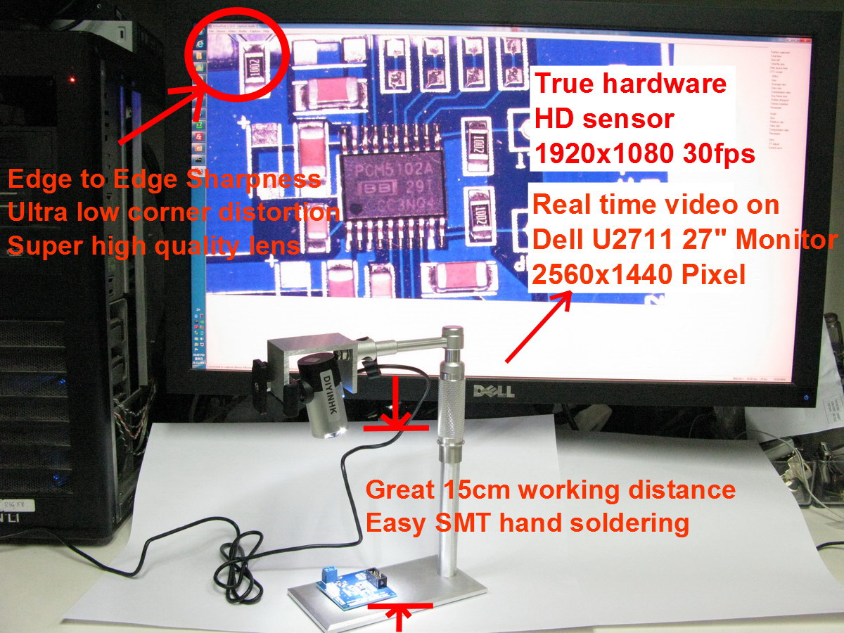
New 1080P USB microscope for easy SMT soldering
Feature:
* 15cm working distance
* 1080P 30fps video, object size is 31mm(1920 pixel) x 17mm(1080 pixel) at 15cm working distance
* Equipped with tailer made megapixel lens, edge to edge sharpness
* UVC compatible, no driver is needed in windows 7 for 1080P operation
* True hardware 1920*1080 pixel high quality non-interpolate Large CMOS sensor
* Aluminum Stand with precision height adjustment
Last edited:
Here: "True 1080P High quality microscope for SMT soldering" at DIYinHK http://www.diyinhk.com/shop/home/48-1080p-smt-microscope.html
As best I can tell from the ad it looks like a very capable tool. The aluminum stand caught my attention - if it's manufactured with as much attention to detail and well-fitted components as the pictures seem to show, it speaks well for the entire instrument. It's also US$300 in price. Small change by commercial standards, but rather pricey for the majority of hobbyists.
I mentioned a lower-cost alternative (including a sample display image) at http://www.diyaudio.com/forums/anal...screte-opamp-open-design-275.html#post3389027 The company that makes it (IPEVO) now has two newer models which look interesting, though I don't know if they would be especially well suited to working SMT boards.
Dale
As noticed at eevblog this is a Microsoft Lifecam Studio with a lens attached to the front!
FS: New 1080P USB microscope for easy SMT soldering - Page 1
FS: New 1080P USB microscope for easy SMT soldering - Page 1
As noticed at eevblog this is a Microsoft Lifecam Studio with a lens attached to the front!
FS: New 1080P USB microscope for easy SMT soldering - Page 1
yes, it's microsoft 1080p lifecam studio! the sensor quality is guarantee
after trying many sub100 vga(fake megapixel) microsope, I decided use sensor from famous brand
microsoft 1080p lifecam studio =$99.95MSRP (~60 market)
Stand = ~60+30(added parts)
megapixel lens =90
plus testing and assembly
if there are enough person have interest, and just order the parts for diyer to modification, the cost can be down at less 70%(not including lifecam studio).
but be careful when modding, I permanently damaged 3 lifecam studio during modification before perfect mod. of every later one
Last edited:
Is it mac compatible?
/U.
it's based on microsoft lifecam studio 1080p,
I found there is review using this cam in mac
mactaris.blogspot.com/2012/05/microsoft-lifecam-studio.html
it should be the same
Last edited:
yes, it's microsoft 1080p lifecam studio! the sensor quality is guarantee
after trying many sub100 vga(fake megapixel) microsope, I decided use sensor from famous brand
microsoft 1080p lifecam studio =$99.95MSRP (~60 market)
Stand = ~60+30(added parts)
megapixel lens =90
plus testing and assembly
if there are enough person have interest, and just order the parts for diyer to modification, the cost can be down at less 70%(not including lifecam studio).
but be careful when modding, I permanently damaged 3 lifecam studio during modification before perfect mod. of every later one
I missed to add this one also has Cree LED lighting = ~30
but i decide to remove it for a more friendly lower cost in future. The LED make it more convenience to use, but the assembly process is harder. Normally, all external lighting can be used but not as compact as builtin lighting
Moved to Vendor's Bazaar. If this becomes an open DIY project, we will move it back
Thanks, it should be better to broken it as parts for diyer to mod themselve, although it's not easy but it's fun, and I have not spare time to mod too many for others.
hi,
does anyone know what the approximate output impedance of the iso7640fm is? i would like to choose appropriate value dampening resistors to match the output to the ~100ohm characteristic impedance of the cat6 cable i will be using as the transmission line.
thanks,
-matt
does anyone know what the approximate output impedance of the iso7640fm is? i would like to choose appropriate value dampening resistors to match the output to the ~100ohm characteristic impedance of the cat6 cable i will be using as the transmission line.
thanks,
-matt
I'm still having trouble getting my isolator to work
I've taken some powered voltage readings that clearly show something is very wrong. My solder joints are not the prettiest on this effort but all measure well for continuity.
Originally the PC would not recognise the Amanero when the isolator was in place. I replaced U1 and now the PC does see it and plays happily.
However still no sound.
The voltage readings are as follows, taken powered with boards stacked. U2 & U3 not populated.
----------ISO IN----- ISO OUT
power ---- 3.3v -------- 0.7v
data ------ 0.8v -------- 0v
bclk ------ 1.63v ------- 0v
fslk ------- 1.63v ------- 0v
mclk ------ 1.65v ------- 0v
Any ideas folks?
TIA
- Home
- Vendor's Bazaar
- diyinhk Store