Hi David,
Your Toroidy is probably 240V only (not 120V/240V), so there's no centre tap on the primary side. The wiring you've shown is correct.
If you put another 2-terminal junction block on the other wire, you can then wire the line snubber capacitor between the two blocks.
Cheers,
Jeff.
Your Toroidy is probably 240V only (not 120V/240V), so there's no centre tap on the primary side. The wiring you've shown is correct.
If you put another 2-terminal junction block on the other wire, you can then wire the line snubber capacitor between the two blocks.
Cheers,
Jeff.
Hi David,
Your Toroidy is probably 240V only (not 120V/240V), so there's no centre tap on the primary side. The wiring you've shown is correct.
If you put another 2-terminal junction block on the other wire, you can then wire the line snubber capacitor between the two blocks.
Cheers,
Jeff.
You mean this?:

Thanks for the quick answer.

...
Try to cover all the exposed mains wiring with at least one layer of High Voltage insulation.
Heat-shrink tubing (polyolefin) works well here.
Dabenza is in the EU
CL60 @ ~10ohms on a 110/120Vac supply limits the peak current to ~ sqrt(2)*115/10 =~16Apk
That would usually not rupture a T6.3A fuse and may even allow a T5A fuse to survive repeated cold starts (for a 600VA transformer).
Now calculate what happens using a single CL60 on a 220/240Vac supply.
And to make the matter worse, the required fuse on this higher voltage supply would be T2.5A or T3.15A to feed power to the same VA transformer.
Last edited:
Remember the CL60 are at mains voltage. Don't touch them (to feel if they are warm or hot) when powered ON.
Try to cover all the exposed mains wiring with at least one layer of High Voltage insulation.
That's a hell of an advise, thank you Andrew. I didn't intent to touch absolutely anything while switched on. I'm no electrician, and I don't run risks.
Hi David,
What size Toroidy did you get? I just got a 300VA (for an F3) and a 500VA (for an F5) today. I measured a 5.5ohm primary on the 300VA, and a 2.5ohm on the the 500VA.
For the 500VA I'm going to use a pair of CL60s as in your drawings. (This will give a total of 22.5ohms on the primary side.)
But for the 300VA, I think a single CL70 (16ohms) is sufficient. (16 + 5.5 for 21.5ohms on the primary side).
If you've already go the CL60s they'll no doubt be fine; just thought I'd mention it in case you have one of the smaller transformers and might want to go with a single CL70.
Cheers,
Jeff.
[Edit: it's also possible we're being overly cautious. I note that the 110V FirstWatt production units use a CL60 for each primary winding, in effect paralleling them. That means each primary is allowed to suck down about 13A for a total of 26A. A single CL60 on the 240V 300VA transformer does better (22A), while a single CL60 even on the 240V 500VA transformer is equivalent (26A). Or course the 240V fuses are 1/2 the amperage of the 110V ones, so similar inrush currents may be a bad idea.....]
Last edited:
Hi Jeff, i'm building an F6 and I ordered a 400VA. So I suposse from what you say that two cl60 would be just fine. What do you think? I'm deeply sorry my knowledge in electronics is just not enough to follow your last paragraph. I understand ampers are higher in US, but honestly I don't want to talk about something I don't really know, not to add bad info in this forum. I just let the wise men talk.
No need to be sorry. Just let the stuff soak in. Before you know it, you'll actually be understanding a lot of it.
I did some more research. Peak loading of transformer inrush is less than 1/4 of a cycle, so less than 5ms at 50hz. (Inrush Current)
A 1.25A slow-blow can take about 12A for that duration, while a 2.5A slow-blow can take about 20A. (http://www.littelfuse.com/~/media/electronics/datasheets/fuses/littelfuse_fuse_218_datasheet.pdf.pdf)
Absolute max current draw from a single CL60 into a 400VA transformer will be 23A, but a transformer followed by a CRC filter will draw considerably less.
So you may need a 2.5A fuse with a single CL60.
A pair of CL60s will limit max to 14A, again with actual considerably lower. No issue with a 1.25A slow-blow here.
So I think I've changed my mind. I'd start with a single CL60 and a 1.25A slow-blow. If it blows fuses, either put in a second CL60, or use a 2.5A slow-blow fuse.
Cheers,
Jeff.
No need to be sorry. Just let the stuff soak in. Before you know it, you'll actually be understanding a lot of it.
I did some more research. Peak loading of transformer inrush is less than 1/4 of a cycle, so less than 5ms at 50hz. (Inrush Current)
A 1.25A slow-blow can take about 12A for that duration, while a 2.5A slow-blow can take about 20A. (http://www.littelfuse.com/~/media/electronics/datasheets/fuses/littelfuse_fuse_218_datasheet.pdf.pdf)
Absolute max current draw from a single CL60 into a 400VA transformer will be 23A, but a transformer followed by a CRC filter will draw considerably less.
So you may need a 2.5A fuse with a single CL60.
A pair of CL60s will limit max to 14A, again with actual considerably lower. No issue with a 1.25A slow-blow here.
So I think I've changed my mind. I'd start with a single CL60 and a 1.25A slow-blow. If it blows fuses, either put in a second CL60, or use a 2.5A slow-blow fuse.
Cheers,
Jeff.
Hi Jeff! Things are soaking too slow! Thanks for the kind couraging words.
I'm not using slow blow fuses, so I don't know if I should be using one cl60 or rather two in series. Probably I'll go for two. I've got fuses ranging 1.6 to 3 ampers. I'll try with the lowest value and see.
Kind regards,
David.
Sorry about a rookie question. Does one PSU board set require single AC secondary output from a transformer? Or do I need a transformer with 2 secondaries to build the complete PSU?
As standard you need a 2x18v transformer. The middle windings get tied to ground and the 2 other ends get rectified and smoothed. That's how you get plus and minus ~23v supplies.
Alternatively you can use 2 separate single 18v transformers.
I would think that any attempted solution to use, say, a single 36v transformer with a couple of resistors to tie the centre to ground would probably not be a good idea here but I couldn't tell you why.
Question on star-on-star grounding
I am preparing to build a pair of 200W mono amps. I will be using diyaudio’s Universal PSU V3 cards in the power supply. In Bob Cordell’s book Designing Audio Power Amplifiers, in the section on power supplies, he suggests using what he calls star-on-star grounding techniques. I have read all the posts in this thread and have not found a discussion on star-on-star grounding. I have two questions that I hope are not too naive.
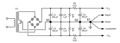
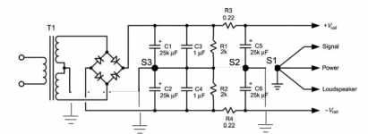
Question one has to do with schematic notation when showing star-on-star grounding. In the first attachment I have copied a figure from Cordell’s book where he shows the multiple grounds as S1, S2 and S3. Am I correct in assuming that the actual wiring will look like the schematic shown in the second attachment where the individual grounds are brought to a single star ground point?
Question two – Based on the schematic and inspection of the board for the Universal PSU it looks like it will not be possible to implement a wiring scheme where the grounds for the two sides of the CRC filters are separated. Is that correct?
Any advice would be appreciated.
Thanks
ceulrich
I am preparing to build a pair of 200W mono amps. I will be using diyaudio’s Universal PSU V3 cards in the power supply. In Bob Cordell’s book Designing Audio Power Amplifiers, in the section on power supplies, he suggests using what he calls star-on-star grounding techniques. I have read all the posts in this thread and have not found a discussion on star-on-star grounding. I have two questions that I hope are not too naive.
Question one has to do with schematic notation when showing star-on-star grounding. In the first attachment I have copied a figure from Cordell’s book where he shows the multiple grounds as S1, S2 and S3. Am I correct in assuming that the actual wiring will look like the schematic shown in the second attachment where the individual grounds are brought to a single star ground point?
Question two – Based on the schematic and inspection of the board for the Universal PSU it looks like it will not be possible to implement a wiring scheme where the grounds for the two sides of the CRC filters are separated. Is that correct?
Any advice would be appreciated.
Thanks
ceulrich
Attachments
I know this has been brought up previously however I couldn't find a satisfactory answer from the older discussion. Could anyone shed the light as to why we should be using diodes vs bridges?
The price of a 30A/200V diode is roughly $2.5, you need 8 of them
Digi-Key Part Number F7374-ND
The price of a bridge with similar specs is $4, you need 2 of them
Digi-Key Part Number 1242-1271-ND
What do I get when I go with diodes? Any benefits other than presumable greater variety of specs that they come in?
Here is my rookie guess:
Why go with bridges? -
simpler design, less space, cheaper (no wonder they are universally adopted)
Why go with diodes? -
better thermal characteristics (4 heat sinks do a better job than one)
some flexibility (schottky is a good diode, can't find a matching monolithic bridge)
Any input on this?
Schottky vs monolithic bridge
Hello reedcat, seems like there is little interest in either of our questions, we may have posted to the wrong thread.
So I thought I would give you my opinion on yours. If I were building a power supply for a device that did not draw a lot of current, like a preamp, I would use Schottky diodes. And I have done that on a number of my builds over the past few years. However, if I were building for a power amp or anything that draws a fair bit of current, and would require heatsinks on the Schottkys, I would always go for the monolithic bridge. The main reason is cost.
Cheers,
ceulrich
Your left diagram is correct. S1 in this left diagram is the Main Audio Ground (MAG).I am preparing to build a pair of 200W mono amps. I will be using diyaudio’s Universal PSU V3 cards in the power supply. In Bob Cordell’s book Designing Audio Power Amplifiers, in the section on power supplies, he suggests using what he calls star-on-star grounding techniques. I have read all the posts in this thread and have not found a discussion on star-on-star grounding. I have two questions that I hope are not too naive.
Question one has to do with schematic notation when showing star-on-star grounding. In the first attachment I have copied a figure from Cordell’s book where he shows the multiple grounds as S1, S2 and S3. Am I correct in assuming that the actual wiring will look like the schematic shown in the second attachment where the individual grounds are brought to a single star ground point?
Question two – Based on the schematic and inspection of the board for the Universal PSU it looks like it will not be possible to implement a wiring scheme where the grounds for the two sides of the CRC filters are separated. Is that correct?
Any advice would be appreciated.
Thanks
ceulrich
Do not use the right diagram. Routing the wires to a remote star increases the loop AREAS and thus increases the EMI.
Last edited:
I have a (perhaps) similar case. I have an F3 board I'm designing on which I've separated the power ground (to the Cmultiplier and Aleph current source), the signal ground, and the speaker ground. The plan was to run 3 separate wires from these three grounds back to the PSU board. Good idea, or bad?
Thanks,
Jeff.
Thanks,
Jeff.
Attachments
- Home
- Amplifiers
- Power Supplies
- diyAudio Power Supply Circuit Board v3 illustrated build guide