Right, got a prompt answer back today
"Transformer inside is isulated by the epoxy. You don’t have to earth the stainless steel box.
Green/yellow wire is the connenction of interwinding copper shiled – it should be grounded."
I think normally these are mounted through the box with the pretty steel case showing but its inside so ill have to live with it not being earthed. It is covered by the psu board so im very unlikely to touch it anyway even if it were to go live. Which Ive been careful to make sure wires carrying live mains are mechanically connected securely and cant came into contact with it.
Im more worried about the exposed mains voltages on the soft start board. I have put insulation tape over the exposed connectors.
Anyway,
The humming has now stopped. Silent. Cured! Hooray! Im also hoping its cured what i thought was a problem with my preamp and the old tx was somehow throwing some kind of interference back at it. I suspect this is wishful thinking. I cant see how the a fault with the tx in the power amp could change sides when i swap the inputs round.
Sorted the power switch wiring so now both the neutral and live switch off. Short wires to the filter and removed the dc blocker. I dont need it now!
The amp is also sounding better. Clearer at low level and soundstage/imaging has improved on initial listen.
Thanks all who've been able to help!
I have purchased other PSUs for some of my amps - rectifiers were made from to-247 devices - the smaller of the 2 contained a bleeder and the larger contained pi filter. Neither had both and neither had any ringing which I guess means that the PSU doesn't need to be snubbed - i assume because the amp has a solid PSRR? I wanted to try these boards out because well, lets be honest the quality of them and modularity is a bargain compared to rolling my own and it allows me to have options like snubbing if i want to add that feature and test out a few things before rolling my own. I may use a pair of pi filters for this - my rails are running on +-67VDC. My diodes have already been ordered and I have them here, as well as the caps that I need for this project.
1) Since the small form PSU that I have used before that had 4 10,000uF caps didn't have a pi filter, I imagine I can use jumpers and avoid the need...the larger unit used .2r resistor while the build guide recommends .47r. Can I use a .2r resistor since I know that it works well in my circuit and will not effect voltage drop as much as the other values? I also would like to use the mills MRA 5s as they are non magnetic and non inductive - They are 5 W rated as opposed to 3 W rated...I am assuming this would allow me to have a better and wider SOA rather then redistricting current? please correct me if I am incorrect and should in fact use a 3w resistor rather then a 5w.
2) I read an older build guide (v1) that recommended using the rail voltage x .01 for the resistance value using 67v rails, my bleeders should be at 6.7kr - again to make sure it is over built can I use a 5w resistor rather then a 3w resistor?
3) LED colors - It is speced for red or green, however I have a large number of blue LEDs at 5mm, I don't imagine it making a difference however I saw amp schematics referencing colored LEDs for the bias portion. The current use is identical from what i remember reading on my LEDs so please let me know if I am am OK using these?
4) LED Dropping resistor is speced at 4.7 to 10k. I imagine any of those values are ideal at 1/4w?
5) output snubber cap and and output snubber resistor - pretty self explanatory
6) input snub cap and resistor - the page i was directed to had a lot of different math I have not done since high school and college so I am little lost - Can i use 470 ohms and a 3900pf resistor? conversely can I just jump this out for now and forget it existed and revisit if needed since the original power supply didn't have it? I have seen number all over the place for snubbers on the input and i imagine it is a case by case situation based on performance. It many not be needed in this circuit and I would rather omit it if i can.
Please advise,
Jared
1) Having a resistor of greater dissipation is never a bad thing in a PSU.
2) As above.
3) It's used as a light, so choose whatever color you like.
4) 10K 1/4W will be fine.
5) Leave empty. (I wish the pads weren't even there, but that's me...)
6) DO NOT JUMPER if you choose to not use input snubber. Leave empty.
2) As above.
3) It's used as a light, so choose whatever color you like.
4) 10K 1/4W will be fine.
5) Leave empty. (I wish the pads weren't even there, but that's me...)
6) DO NOT JUMPER if you choose to not use input snubber. Leave empty.
Power Supply is hissing and spitting at me...
I'm using spade connectors crimped on to the wires coming from the transformer secondary. One of them has started sparking where it's connected to the rectifier block (large blue wire on the right). I re-seated and De-Oxited all of them but it's still doing it. It seems to do it more on startup, then settle down. There is no scoring of the metal, no evidence of excessive heat being produced.
Should I just solder these, or is this indicative of a problem with the rectifier?
Attachments
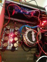
Bad connection, spade terminals should be very tight if you insist on using them
Thanks, I tightened them up and it stopped doing it. I'll have to get around to soldering but I like to be able to disassemble it.
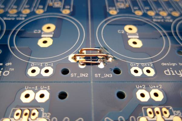
Hi everyone, I didn't want to start a thread about my question, because I find it unnecessary, so here it goes. I'm building a PSU based on the latest board here at diyaudio for an F6 amp, and I'm using the diode bit from the board. The thing is I'm bad at electronics (call me crazy), but I'm reading every tutorial available, and getting help' from friends. Now, I've seen contradicting pictures about the diode bit. As far as I understand, my rectifier diodes should mount like this. I put pictures of both sides:


The rectifier diodes are called F30UP20S, fast recovery diode, 600V 30A. Left leg is cathode, and right, anode, according to data sheet. Am I doing it correctly?
And another thing, as I'm using the green connectors on the photo below, should I better connect all the bridges between grounds, even if I connected the black wire on the photo?

Many thanks, and sorry for the amateurish questions.
The rectifier diodes are called F30UP20S, fast recovery diode, 600V 30A. Left leg is cathode, and right, anode, according to data sheet. Am I doing it correctly?
And another thing, as I'm using the green connectors on the photo below, should I better connect all the bridges between grounds, even if I connected the black wire on the photo?
Many thanks, and sorry for the amateurish questions.
I have read and re-read this (entire) forum, but cannot definitively tell exactly how to connect the 18V AC leads from my transformer to the PSUv3 board using the diode rectifier bridge. I've posted a photo of my current build below -- and indicted what I *think* I understand about how this should be connected to the 18V AC input. I know this is a trivial question and one I should be able to figure out (or infer) but I simply don't feel confident that I'm understanding this correctly. Thank you in advance!
Did you get any answer to this? was your wiring correct? sometimes is impossible to get an idea of something so simple as this. There is info about everything, but it seems that the most basic and important things are disregarded.
Pin one of your diodes is Cathode, and need to be in the center hole, as you have correctly done.
You should have most or all of the ground links connected, the one black wire isn't enough -
Thank you so much for you answer and your precious help 6L6! You know, I still have questions. Regarding the capacitor used with the CL60,

the value is a bit confusing: it is claimed to be 0.0033uF, that is 3.3nF, that is 3300pF, do I understand well?
Would this cap be the right one? Mentioning I'm under 220Vac in Spain:
FG26X7R2J332KNT06 TDK | Mouser Espana
Last edited:
Hi Dabenza,
You are correct on the uF/nF/pF conversions. However, the cap link you gave isn't a very good choice for a couple of reasons:
1) Caps across the mains should be safety rated. In particular, those that go across live/neutral should be X1 or X2, while caps that go from one of live/neutral to ground should be Y1 or Y2.
2) Ceramic caps are very noisy. Might not matter as a mains snubber, but better to just leave them for non-audio applications. (There is a class of ceramic caps known as NP0 or C0G which are OK for audio.)
Here's a better choice: PME271M433MR30 KEMET | Mouser Ireland
Cheers,
Jeff.

Hi Dabenza,
You are correct on the uF/nF/pF conversions. However, the cap link you gave isn't a very good choice for a couple of reasons:
1) Caps across the mains should be safety rated. In particular, those that go across live/neutral should be X1 or X2, while caps that go from one of live/neutral to ground should be Y1 or Y2.
2) Ceramic caps are very noisy. Might not matter as a mains snubber, but better to just leave them for non-audio applications. (There is a class of ceramic caps known as NP0 or C0G which are OK for audio.)
Here's a better choice: PME271M433MR30 KEMET | Mouser Ireland
Cheers,
Jeff.
It's clear! And ordered! What a sickness we have... thank you very much folks.
CL60 with toroidy transformers and 240Vac
More questions arise as I move forward. I've been reading every bit of this thread and I'm nos sure of the correct wiring. the thing is I've purchased a toroidal from Toroidy, and they only have 3 pairs of wires, two for the 18V needed for my F6 and only one pair (same color) for the mains. So, in order to use the NTC CL60, I only come to this:

As is AC, I suppose it doesn't matter which wire I attach the cl60 to, as I cannot know which one is the live or the neutral. But, according to Sir AndrewT, we should only put the inrush current limiter on one of the mains. I use two in series as AndrewT recommended for 220Vac. Well, am I doing something wrong here?
There is still the capacitor missing, but I honestly don't know where it should fit on this layout.
All your help is greatly appreciated.
David.
More questions arise as I move forward. I've been reading every bit of this thread and I'm nos sure of the correct wiring. the thing is I've purchased a toroidal from Toroidy, and they only have 3 pairs of wires, two for the 18V needed for my F6 and only one pair (same color) for the mains. So, in order to use the NTC CL60, I only come to this:
As is AC, I suppose it doesn't matter which wire I attach the cl60 to, as I cannot know which one is the live or the neutral. But, according to Sir AndrewT, we should only put the inrush current limiter on one of the mains. I use two in series as AndrewT recommended for 220Vac. Well, am I doing something wrong here?
There is still the capacitor missing, but I honestly don't know where it should fit on this layout.
All your help is greatly appreciated.
David.
- Home
- Amplifiers
- Power Supplies
- diyAudio Power Supply Circuit Board v3 illustrated build guide