However, the Honey Badger will work well with different rail voltages and transformers. However, the build guide is a bit shy on this point. I don't know the sensible limits for optimal operation, and I often read that lower PSU voltages are recommended for low impedance speakers. I have to admit that I don't understand this recommendation.
In my (slightly simplified) view, the PSU voltage defines the limit of the output voltage where the amp will start clipping (ignoring the transistor losses). Of course, for a given output power, low-impedance loads tend to draw more current and at lower voltage swings than high-impedance loads. But this alone (again in my view) does not warrant a recommendation for lower supply voltages – there must be some other aspects that come into play here, and I don't understand what they are. I'd say it would best to make sure the power supply provides enough voltage for high-impedance loads and has sufficient capacity for high currents to drive low-impedance loads.
Well, maybe my thoughts are all wrong (and somebody please correct me).
In any case, it would be cool if the build guide could be expanded with some hints and explanations about dimensioning a suitable power supply.
A simple explanation is that some of the power supply rail voltage is dropped across the load (speaker) and some across the amplifier power transistors. The amount of power dropped across the power transistor is proportional to the rail voltage.
For a low impedance speaker a higher proportion of the voltage is lost across the power transistors for the same output power across the load. This loss takes the form of heat in the power transistors (and some other internal effects) and this may cause the transistor to fail. For a detailed explanation research transistor safe operating area.
The result is that if you have an excessive rail voltage but want to run low impedance speakers at high power you may never reach the peak rail voltage before your transistors fail. By reducing the rail voltage you can put out more power so long as the rail voltage is still high enough to provide sufficient power (voltage and current) to the speakers.
You can increase the peak power that can be output by increasing the number of output transistors. Insufficient heat sinking can reduce your power output.
The Honey Badger project allows you to optimise for different situations and speaker impedances. My calculations were based on 6 ohm loads for some active speakers I hope to build but also based on the power supply voltages I could afford. If you want maximum power for an 8 ohm load look for a 60V rail. If you want to run 4 ohm speakers look for more like 40-45V. Those figures are from memory and were discussed somewhere in the hundreds of pages of design and build threads.
I hope some of that makes sense.
I finally completed my build of HB project. I used MJL4302A/MJL4281A output devices and put everything in a roomy Dissipante 5U chassis. I used a single Avel 800VA 45-0-45 toroidal transformer connected to 2 universal PSU boards and used 80V 12.000uf capacitors for a total of 48000uf per rail per channel. I built and installed the DC speaker protection board but for the soft start board I went with a ebay Chinese soft start board that includes overtemp protection using a pair of temp sensors. I try not to use ebay china parts but these little soft start boards I have used often and they seem to work very well.
The listening test of this amp connected to basic pair of Klipsch RP-280F was pretty amazing. I compared it to my Adcom GFA 5500 and Mitsubishi DA-A15 and it blew them away. I know my audio gear is on the low end of the spectrum compared to most on this forum but wanted to give praise to the Honey Badger amp for its great sound.
This is only the second amplifier I have built and thanks to the build guide and this forum the build was pretty simple and when finished and put together the initial power up showed no problems or errors so have to give credit to diyAudio for their products!
An externally hosted image should be here but it was not working when we last tested it.
I finally completed my build of HB project. I used MJL4302A/MJL4281A output devices and put everything in a roomy Dissipante 5U chassis. I used a single Avel 800VA 45-0-45 toroidal transformer connected to 2 universal PSU boards and used 80V 12.000uf capacitors for a total of 48000uf per rail per channel. I built and installed the DC speaker protection board but for the soft start board I went with a ebay Chinese soft start board that includes overtemp protection using a pair of temp sensors. I try not to use ebay china parts but these little soft start boards I have used often and they seem to work very well.
The listening test of this amp connected to basic pair of Klipsch RP-280F was pretty amazing. I compared it to my Adcom GFA 5500 and Mitsubishi DA-A15 and it blew them away. I know my audio gear is on the low end of the spectrum compared to most on this forum but wanted to give praise to the Honey Badger amp for its great sound.
This is only the second amplifier I have built and thanks to the build guide and this forum the build was pretty simple and when finished and put together the initial power up showed no problems or errors so have to give credit to diyAudio for their products!
An externally hosted image should be here but it was not working when we last tested it.
Your pictures does not load here.
The Honey Badger sound great on Klipsch RP280, I also built mine with 45v transformers to drive some bookshelf speakers. I tested it on my RP280s first and ended up using it on the 280s instead and sell my Sunfire 300x2.
I also used china soft starts for a while, but never found them stable. Some times they would trip the circuit breaker during power on. I can recommend the 21st century protection board to get both soft start and speaker protection at the same time.
Transformer shielding
While I was building my HB, I was ordering a custom transformer for it, since I also needed 24V AC for my speaker protection board.
The result is two 45V/12A secondaries, and a 24V/3A
Why 3A secondary? you might ask
The answer is simple: As soon as I told the transformer winder that It is going to be made for an amplifier, he offered me to oversize the 24V secondary for free to not to make so much electromagnetism near the transformer itself.
Tip of the day:
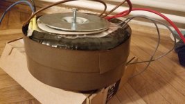
When I went for the transformer, as I got there, I asked for additional SCRAP MU METALS.
They happily gave me like 5 meters, since there is always some scrap material in the process of making toroidal transformers.
Why do you need Mu metal?
Because if you care about fidelity, and ultimate sound quality, you should cover your transformer first with a lot of insulation tape (not to short any wires), then with the mu metal, which will act like a shield against the electromagnetic force.
Simply mount them with double sided tape, and voilá, you shielded your transformer more, thus making easier to make the cable management.
While I was building my HB, I was ordering a custom transformer for it, since I also needed 24V AC for my speaker protection board.
The result is two 45V/12A secondaries, and a 24V/3A
Why 3A secondary? you might ask
The answer is simple: As soon as I told the transformer winder that It is going to be made for an amplifier, he offered me to oversize the 24V secondary for free to not to make so much electromagnetism near the transformer itself.
Tip of the day:
When I went for the transformer, as I got there, I asked for additional SCRAP MU METALS.
They happily gave me like 5 meters, since there is always some scrap material in the process of making toroidal transformers.
Why do you need Mu metal?
Because if you care about fidelity, and ultimate sound quality, you should cover your transformer first with a lot of insulation tape (not to short any wires), then with the mu metal, which will act like a shield against the electromagnetic force.
Simply mount them with double sided tape, and voilá, you shielded your transformer more, thus making easier to make the cable management.
Attachments
Hi Obisix,
-Chris
I don't understand how this would be true. I'm not disagreeing with you, I just don't understand how making a winding for higher current would reduce the magnetic flux around the transformer.... he offered me to oversize the 24V secondary for free to not to make so much electromagnetism near the transformer itself.
-Chris
Maybe he meant more windings, less regulation?
This is what I meant! Sorry, my english skills are not really great!
Sounds like you have great luck Obisix, I don't know why anyone would give away even just 5 meters of mu metal. Maybe here in the States we are just pressed for cash.
I don't know about the States, but here in Hungary, everyone is helping each other since we know that our salary is really bad, mine is 300 USD a month (full time job). So maybe yeah, but it is worth a try to ask for it!
This is what I meant! Sorry, my english skills are not really great!
I don't know about the States, but here in Hungary, everyone is helping each other since we know that our salary is really bad, mine is 300 USD a month (full time job). So maybe yeah, but it is worth a try to ask for it!
I don't think it's mu metal if it's used for toroidal transformer production.
Almost certainly a high silicon steel designed specifically for 50/60Hz transformers.I don't think it's mu metal if it's used for toroidal transformer production.
One easy way to test that theory is to bend that metal. If it bends easily and holds it's shape, it might be mu metal. If not, probably steel.
-Chris
It bends easily, and holds it's shape. Also the brownish color turns white immediately after the first bend, it crystallizes easily. The guy making the transformer told me that this is Mu metal, what he uses in toroidal transformer making process. "This is the material we use for the core" he told me.
Hi Obisix,
I can't figure out why he used that for a core material, but Jeff's right. It certainly isn't what you would consider using for a core! It would only generate eddy currents, not a magnetic flux worth talking about. But hey, it sounds like you have some mu-metal there.
Your English is better than most, so don't fret.
-Chris
I am trying to figure out how and where the Honey Badger was improved since the build guide was written (I have the V2.4 boards).
Here are a few things I found in the main thread, but I am not sure if this is everything as the thread is a bit long:
Is this list complete? And what's the "diode fix"?
(And would it be a good idea to update the build guide?)
Here are a few things I found in the main thread, but I am not sure if this is everything as the thread is a bit long:
- The addition of the Baker Clamp Diode ("D-BC" option): use a BAV21 or BAV20.
- R12 and R13 values (VAS CCS): use R12=6.8kΩ and R13=10kΩ (instead of R12=10kΩ and R13=15kΩ in the build guide).
- What's the "diode fix"? What needs to be changed where, how, and why?
Is this list complete? And what's the "diode fix"?
(And would it be a good idea to update the build guide?)
Hi,
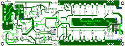
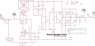
I made this layout based on the attached sch.
Any suggestions?
thank you.
Eric
Spread your output devices out. The center ones are going to run hotter than the outer ones and current hog.
- Home
- Amplifiers
- Solid State
- diyAB Amp - The "Honey Badger"