The purpose is to help a CRC supply throughout the wide dynamic range of a powerful amplifier. So, the plan is to reduce noise, not bass. It would be easier to say how to select those parts:what is the purpose of the resistor and the diode?
Optimize the resistor value for best audio quality at modest/normal levels
Optimize the bypass diode forward voltage drop (0.3v~0.9v) for best audio quality at full blast
That is very doable for the high capacitance tank/reservoir section. Thanks!for me, tie all caps together for the positive and negative rails, and make them meet the center tap pad in one place.
Thanks!Personally, I would expect 1) to be preferred in your choices. All PCB traces have resistance proportional to their length (for a given width and thickness).
So, more like this?
Attachments
Hi Daniel,That is very doable for the high capacitance tank/reservoir section. Thanks!
Thanks!
So, more like this?
Firstly, the 3K3 resistors need to be rated at more than 1 watt. This limits the rails to +/- 57.4V DC without a safety margin. You don't mention your chosen rail voltage level. Either increase their resistance, or increase their power rating. I would aim for 75%-80% of their maximum power rating in the interests of reliability.
Secondly, the star connection arrangement to the 0V point on the first three capacitors should possibly be duplicated on the + and - rails.
Last edited:
The 3.3k resistors will matter less than normal line voltage variations will. If you are concerned about them, then you should be even more concerned about whether your mains voltage is constant or not. For the vast majority of applications it doesn't matter, and if it does you should be fixing what's broken.
The 3.3k resistors will matter less than normal line voltage variations will. If you are concerned about them, then you should be even more concerned about whether your mains voltage is constant or not. For the vast majority of applications it doesn't matter, and if it does you should be fixing what's broken.
in my case, mains voltage are never constant, it can be 215 volts in the daytime and 235 volts at night time...but i do my calculations and considerations using the high line case....
But delete that spurious diode in each supply rail.
it is a fashion statement of sorts.....personally i never used them nor will ever....
Isn't the purpose of the "3K3" resistors to discharge the PSU capacitors within a reasonable time period after switch-off to permit safe servicing of the amplifier?
Regardless of mains voltage variations, these resistors need to be correctly dimensioned in order to avoid their overheating. Depending on the selected output configuration, the DC rails may lie between +/- 35 and +/- 85 V DC.
At 85V per rail, each 3K3 resistor will be required to dissipate (85^2) / 3300 = 2.2 W.
Those "discharge" resistors do several things.Isn't the purpose of the "3K3" resistors to discharge the PSU capacitors within a reasonable time period after switch-off to permit safe servicing of the amplifier?
Regardless of mains voltage variations, these resistors need to be correctly dimensioned in order to avoid their overheating. Depending on the selected output configuration, the DC rails may lie between +/- 35 and +/- 85 V DC.
At 85V per rail, each 3K3 resistor will be required to dissipate (85^2) / 3300 = 2.2 W.
The one we want is to discharge the capacitors after Power OFF.
The various things we don't want, include; increasing supply ripple, increasing power dissipation inside a casing, increasing the power drawn from the electricity supplier.
These last three can be very important and can all be avoided.
Use a normally closed relay to connect the discharge resistors during OFF periods.
Use a lower power trigger circuit to switch out the resistors during ON periods.
For reasons of cost and simplicity, there are at least two approaches to mitigate the three disadvantages you mentioned:Those "discharge" resistors do several things.
The one we want is to discharge the capacitors after Power OFF.
The various things we don't want, include; increasing supply ripple, increasing power dissipation inside a casing, increasing the power drawn from the electricity supplier.
These last three can be very important and can all be avoided.
Use a normally closed relay to connect the discharge resistors during OFF periods.
Use a lower power trigger circuit to switch out the resistors during ON periods.
a) omit the resistors altogether and remember to discharge the capacitors manually with resistors before servicing,
b) use higher value discharge resistors and wait until sufficient discharge has occurred.
Indeed, yes.For reasons of cost and simplicity, there are at least two approaches to mitigate the three disadvantages you mentioned:
a) omit the resistors altogether and remember to discharge the capacitors manually with resistors before servicing,
b) use higher value discharge resistors and wait until sufficient discharge has occurred.
I adopt option a)
But I don't need to remember, the caps discharge themselves while driving the amplifier down to silence.
The only situation that comes to mind where this could fail would be with secondary fuses in the main supply rails blowing and leaving the cap/s charged.
Then the red LED shows charge is still there when I open the lid.
Indeed, yes.
I adopt option a)
But I don't need to remember, the caps discharge themselves while driving the amplifier down to silence.
The only situation that comes to mind where this could fail would be with secondary fuses in the main supply rails blowing and leaving the cap/s charged.
Then the red LED shows charge is still there when I open the lid.
Thank goodness for LEDs
") I adopt option 2) but with higher discharge resistance and no LEDs (yet). Good point about the fuses blowing.
I adopt option 2) but with higher discharge resistance and no LEDs (yet). Good point about the fuses blowing.The resistors need to be sized so it has a fast enough time constant. So what is a good one? 30 seconds, 1 minute? Maybe a CCS diode would be a better option than a resistor, as the discharge won't slow down when voltage gets low, so you waste less power for the same speed of discharge.
PS. Dan, you have mail.
PS. Dan, you have mail.
Yes. And, thanks for the calc. Okay, here goes. Because of the amplifier, I'm starting with a voltage estimate of 65vdc.Isn't the purpose of the "3K3" resistors to discharge the PSU capacitors within a reasonable time period after switch-off to permit safe servicing of the amplifier? At 85V per rail, each 3K3 resistor will be required to dissipate (85^2) / 3300 = 2.2 W.
65*65, then divide resistor values in ohms till I come up with 75% of a watt is 5600 ohms. 5k6--is that okay?
Also, in calculating the LED's, 1.8fvd, 65vdc, 7ma, I get 9k, which is likely to need 10k after they get warm. Is that okay?
Hi Dan,Yes. And, thanks for the calc. Okay, here goes. Because of the amplifier, I'm starting with a voltage estimate of 65vdc.
65*65, then divide resistor values in ohms till I come up with 75% of a watt is 5600 ohms. 5k6--is that okay?
Also, in calculating the LED's, 1.8fvd, 65vdc, 7ma, I get 9k, which is likely to need 10k after they get warm. Is that okay?
5K6 / 1W would be fine. It would just take a little longer to discharge the capacitors, but that shouldn't be a problem. Having two resistors, one per rail, means you would "waste" 1.5 watts in total.
For the LEDs, (65-1.8) / 10K would give you 6.3mA forward current and the series resistor would dissipate (I^2 x R) just under 400mW.
it is not just the bleeder resistors that will cause cap discharge at turn-off,
the amp drawing current speeds up the discharge also as it has an idle current,
this together with the bleeder resistor determines bleed down times....
FWIW, i used 8.2k/2watt bleeders in my super leach amp at +-85 volt rails...
the amp drawing current speeds up the discharge also as it has an idle current,
this together with the bleeder resistor determines bleed down times....
FWIW, i used 8.2k/2watt bleeders in my super leach amp at +-85 volt rails...
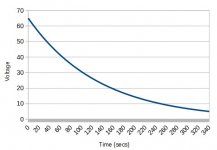
To get an idea of the discharge time, it would take around 340 seconds for 65V rails to drop to 5V due to 5K6 discharge resistors and 23700uF alone.
This ignores the amplifier's operating current and quiescent current drain on the capacitors which would reduce the discharge time as AJT stated. However, a blown fuse between the amplifier and PSU can occur, in which case only the discharge resistor would be effective.
This ignores the amplifier's operating current and quiescent current drain on the capacitors which would reduce the discharge time as AJT stated. However, a blown fuse between the amplifier and PSU can occur, in which case only the discharge resistor would be effective.
Attachments
oops! That's a little hot. LED's die easily in hot conditions.For the LEDs, (65-1.8) / 10K would give you 6.3mA forward current and the series resistor would dissipate (I^2 x R) just under 400mW.
oops. That's a little inconvenient. Or, possibly "most extremely inconvenient" if the LED's also got cooked previously.To get an idea of the discharge time, it would take around 340 seconds for 65V rails to drop to 5V due to 5K6 discharge resistors and 23700uF alone.
Thanks for your help!
Apparently, some things need re-figured.
This inexpensive supply probably isn't supposed to be used at 65V anyway, because too small for the job.
So,
What is the maximum transformer voltage that can be associated with safe use of a power supply board that has 63V caps?
Checking transformer availability, there's 34vac, 35vac, 36vac, 38vac, and 40vac, so how high can we go at maximum, yet assume the 63v caps probably aren't harmed?
We'd probably like to use inexpensive 63v caps on this little supply, and we'd probably like those caps to last a long time.
The answer to that question will let me specify a rail voltage on the schematic, and then afterwards, maybe calculate more sensible resistor values for the drainers and LED's.
Last edited:
oops! That's a little hot. LED's die easily in hot conditions.
oops. That's a little inconvenient. Or, possibly "most extremely inconvenient" if the LED's also got cooked previously.
Thanks for your help!
Apparently, some things need re-figured.
This inexpensive supply probably isn't supposed to be used at 65V anyway, because too small for the job.
So,
What is the maximum transformer voltage that can be associated with safe use of a power supply board that has 63V caps?
Checking transformer availability, there's 34vac, 35vac, 36vac, 38vac, and 40vac, so how high can we go at maximum, yet assume the 63v caps probably aren't harmed?
We'd probably like to use inexpensive 63v caps on this little supply, and we'd probably like those caps to last a long time.
The answer to that question will let me specify a rail voltage on the schematic, and then afterwards, maybe calculate more sensible resistor values for the drainers and LED's.
I don't understand why you think the LED will be hot at only 6.3mA. The power dissipation in the LED will be its Vf x 6.3mA = 1.8 x 6.3 = 11.3mW (some of which will be photons). Only the LED's series resistor will dissipate 400mW.
The maximum transformer voltage for 63V electrolytics will depend on the transformer's regulation and mains voltage variation. What is the quoted regulation figure for the transformer you intend to use and your local mains voltage tolerance?
It isn't for me, so the mains voltage at my house is not important at the moment. When supporting a high power amplifier, I actually wouldn't promote center tap's poorer utilization except for when the transformer is free or low cost. So, this about reemploying low cost used center tap transformers, with the datasheet gone missing. The popular range seems apparent from 28,0,28vac through 36,0,36vac. Is that too high for 63v caps? Would 38,0,38v work alright? Help?The maximum transformer voltage for 63V electrolytics will depend on the transformer's regulation and mains voltage variation. What is the quoted regulation figure for the transformer you intend to use and your local mains voltage tolerance?
- Home
- Amplifiers
- Solid State
- diyAB Amp - The "Honey Badger"