Can you ask them to see if the resistor is magnetic?
Hi Stuart,
Please be informed that this part is not magnetic as per Supplier
Last edited:
1. It is a good demonstration of theory. Remove the ferrite core and it will not cause much more distortion over the 1.5uH inductor.
Since you have remote mounted the inductor, it would be interesting to put it back in place after testing with a linear resistor, and then we will know for sure if any of the nearby steel causes distortion in the inductor. Because we actually can't rule that out unless we have a linear load.
2. Yesterday I replaced the metal film resistor across the output coil in my bench amp with a nonmagnetic one.
3.And that really feels like fudging. I can only imagine Stuart feels the same way if he has been going at this for months to find the solution.
1. I will definitely try that when I get time. Please note that this was an extra inductor that I added in series with the load. I had already soldered back in to the pcb the original inductor in the original location.
2. Please take some photos as a picture speaks a 1000 words.
I never knew there was such a thing as a nonmagnetic resistor. Do you have a part number?
3. I've been taking distortion measurements for over a year now and this has been causing me alot of grief as you know. But I'm really glad that it's helped you find a solution to a issue that you were having. Lets hope it helps other members too.
You can't really tell from looking at things whether they are magnetic. The original coil resistor was a 1/2W carbon film and I used a carbon comp resistor to replace it, but those can still have steel endcaps or steel leads. Same with binding posts. You don't really know until you test it with a magnet.
I can't detect any magnetism from the stainless bolts I used with the EBG resistors with a strong neodymium magnet, and they don't cause any distortion that I can detect. So some grades of stainless seem to be okay.
I'm curious where the Mouser staff gets their information because nowhere on the datasheet does it specify that resistor is nonmagnetic. Maybe they just assume that non-inductive means nonmagnetic? I have been burned in this scenario several times. Maybe you need to clarify.
Last edited:
This looks like a potential candidate for the coil resistor:
Search results for: koa bpr KOA Speer 10 Ohms Current Sense Resistors - Through Hole – Mouser Australia
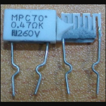
Picture of a similar resistor from Fukushima Futaba is attached.
Although honestly, you may just want to go this way:
QTY:10, EBG (VISHAY) UXP/300 10RK 10 OHM/10OHM 300W FOIL NON-IND.POWER RESISTOR | eBay
You get 10 10ohm resistors. That means if you use one and string 4 more in series, and put that in parallel with the first one, you get an 8ohm resistor. You get 10 resistors, so you can make 2 8ohm resistors and put them in parallel to get 4 ohms. You can put 5 resistors in parallel to get 2 ohms.
Search results for: koa bpr KOA Speer 10 Ohms Current Sense Resistors - Through Hole – Mouser Australia
Picture of a similar resistor from Fukushima Futaba is attached.
Although honestly, you may just want to go this way:
QTY:10, EBG (VISHAY) UXP/300 10RK 10 OHM/10OHM 300W FOIL NON-IND.POWER RESISTOR | eBay
You get 10 10ohm resistors. That means if you use one and string 4 more in series, and put that in parallel with the first one, you get an 8ohm resistor. You get 10 resistors, so you can make 2 8ohm resistors and put them in parallel to get 4 ohms. You can put 5 resistors in parallel to get 2 ohms.
Attachments
This looks like a potential candidate for the coil resistor:
Although honestly, you may just want to go this way.
Purchased.... Done.... $50 shipping. But overall a good deal.
Thanks Keantoken.
I'm curious where the Mouser staff gets their information
They told me they contacted the manufacturer
I don't have an LCR meter so it is a pain to set up the test, but the datasheet gives 80nH:
https://microem.ru/files/2014/09/EBG_UXP300.pdf
https://microem.ru/files/2014/09/EBG_UXP300.pdf
distortion at speaker
If your speaker load is highly inductive will that mean you should expect significantly more distortion? I was hoping to put my Honey on a pair of electrostatics or Maggies. Electostatics are just huge capacitors and the Maggies are just huge inductors.
If your speaker load is highly inductive will that mean you should expect significantly more distortion? I was hoping to put my Honey on a pair of electrostatics or Maggies. Electostatics are just huge capacitors and the Maggies are just huge inductors.
Last edited:
I had the same thought. Maybe I should hook this up to and actual speaker and give it a go. Hopefully I don't blow my speaker....If your speaker load is highly inductive will that mean you should expect significantly more distortion? I was hoping to put my Honey on a pair of electrostatics.
What do you guys think?
The harmonic voltage across the source impedance when driving a nonlinear inductor actually linearizes the flux, so in a speaker it actually reduces magnetic distortion. Hence current drive. But there is suspension and other distortions to worry about, so you never quite know.
Ultimately the impedance of your crossover components is far larger than that of the amplifier, so I would not worry at all.
Ultimately the impedance of your crossover components is far larger than that of the amplifier, so I would not worry at all.
I had the same thought. Maybe I should hook this up to and actual speaker and give it a go. Hopefully I don't blow my speaker....
What do you guys think?
The amp is not malfunctioning and you've tested it many times with a full load. So I don't see why not.
Have a slight transformer hum in mine, it's very low, but I went overkill on the transformers, so I think it's a matter of more not better in this case. It's only audible from a foot or so, and I wasn't even sure it was there until I put my ear on the front of the amp and then clearly audible, but not anything I'm going to worry about or correct.
This is one beast of an amp and I like it's song very much.
JT
This is one beast of an amp and I like it's song very much.
JT
Have a slight transformer hum in mine, it's very low, but I went overkill on the transformers, so I think it's a matter of more not better in this case. It's only audible from a foot or so, and I wasn't even sure it was there until I put my ear on the front of the amp and then clearly audible, but not anything I'm going to worry about or correct.
This is one beast of an amp and I like it's song very much.
JT
toroid or EI? if EI you can try to tighten bolts and nuts, if toroid nothing much to do...
you are correct, this Honey badger is a very good modern day design, Ostripper has a winner in this amp...
Last edited:
Hi Keantoken,This looks like a potential candidate for the coil resistor:
Search results for: koa bpr KOA Speer 10 Ohms Current Sense Resistors - Through Hole – Mouser Australia
Picture of a similar resistor from Fukushima Futaba is attached.
Although honestly, you may just want to go this way:
QTY:10, EBG (VISHAY) UXP/300 10RK 10 OHM/10OHM 300W FOIL NON-IND.POWER RESISTOR | eBay
You get 10 10ohm resistors. That means if you use one and string 4 more in series, and put that in parallel with the first one, you get an 8ohm resistor. You get 10 resistors, so you can make 2 8ohm resistors and put them in parallel to get 4 ohms. You can put 5 resistors in parallel to get 2 ohms.
Those resistors work perfectly.
Thank you so much for helping me and all the other members with the best load resistor to use.
View attachment 948254


 View attachment 948255
Well, I cranked it up tonight until the windows cracked... about the time i reached to turn it down it just stopped. No pop or noise, just nothing. ") I guess I'll have to grab the meter tomorrow and see what I can see.
I guess I'll have to grab the meter tomorrow and see what I can see.
Quick check showed fuses good, but the PS LEDs which should drain down pretty quick stay lighted for an extended time. this one has DC protect boards and soft start, which both appear to be functioning.
I guess I'll have to grab the meter tomorrow and see what I can see. Quick check showed fuses good, but the PS LEDs which should drain down pretty quick stay lighted for an extended time. this one has DC protect boards and soft start, which both appear to be functioning.
Well, I cranked it up tonight until the windows cracked... about the time i reached to turn it down it just stopped. No pop or noise, just nothing.
Quick check showed fuses good, but the PS LEDs which should drain down pretty quick stay lighted for an extended time. this one has DC protect boards and soft start, which both appear to be functioning.
mains fuse?
btw, in my next builds, i wll choose same red color leds so that the drain off after turning the power switch is even...
Last edited:
- Home
- Amplifiers
- Solid State
- diyAB Amp - The "Honey Badger"