I played with an amp today to check out my resistors.
I tracked down what was causing distortion.
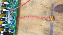
It was a 1" length of steel wire clipped off of some component which I had used in the terminal block to bring the output to some alligator clips. It is strongly attracted to a magnet, like the leads on the capacitors that were lying nearby...
Note that this wire has been clipped off of a component, likely a resistor or capacitor. And the other wire for the other terminal was copper. So just 1" of steel wire was enough to cause 0.002% THD1k at 100W into 4ohm. The effect likely would have rose with frequency.
After doing this my EBG UXP-300 resistors show no distortion that I can see, at either end of the cable from amp to resistors.
I tracked down what was causing distortion.
It was a 1" length of steel wire clipped off of some component which I had used in the terminal block to bring the output to some alligator clips. It is strongly attracted to a magnet, like the leads on the capacitors that were lying nearby...
Note that this wire has been clipped off of a component, likely a resistor or capacitor. And the other wire for the other terminal was copper. So just 1" of steel wire was enough to cause 0.002% THD1k at 100W into 4ohm. The effect likely would have rose with frequency.
After doing this my EBG UXP-300 resistors show no distortion that I can see, at either end of the cable from amp to resistors.

More Results
Hi Keantoken,
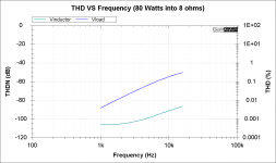
I ran some more tests as shown in the images with no real change in the distortion levels.
THD VS Frequency shows the distortion levels with the simplified output connections as shown in my last post.
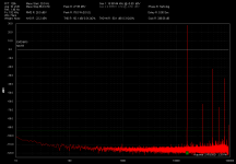
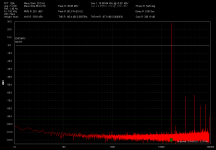
The other two plots show the distortion of the remotely mounted
zobel network coil.
The first shows the THD measured at the inductor test point on the PCB.
The second shows the THD measured across the load resistor.
I will now run some resistor tests using some 10w 8.2 ohm wire wound ceramic resistors I have here at home.
Hi Keantoken,
I ran some more tests as shown in the images with no real change in the distortion levels.
THD VS Frequency shows the distortion levels with the simplified output connections as shown in my last post.
The other two plots show the distortion of the remotely mounted
zobel network coil.
The first shows the THD measured at the inductor test point on the PCB.
The second shows the THD measured across the load resistor.
I will now run some resistor tests using some 10w 8.2 ohm wire wound ceramic resistors I have here at home.
Attachments
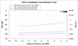
Final Results
Hi @Keantoken,
Well I have finally cracked it, This has been a puzzle that I have been trying to solve for at least 12 months now and thanks to you and some other members who have supported my efforts I now can report the true distortion levels of this amazing amplifier. I was just about to give up honestly but you gave me that final encouragement and support that I need to motivate me to keep going.
A big thank you to Johno, Harry and Sandro for their support as well.
It was the load resistor all along.
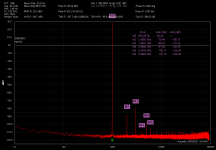
The really interesting part was that the distortion is even lower now that what I first measured pre-inductor.
Amazing..
The distortion at 1K is not actually measurable as its lower than the actual loopback distortion of the QA401.
Hi @Keantoken,
Well I have finally cracked it, This has been a puzzle that I have been trying to solve for at least 12 months now and thanks to you and some other members who have supported my efforts I now can report the true distortion levels of this amazing amplifier. I was just about to give up honestly but you gave me that final encouragement and support that I need to motivate me to keep going.
A big thank you to Johno, Harry and Sandro for their support as well.
It was the load resistor all along.
The really interesting part was that the distortion is even lower now that what I first measured pre-inductor.
Amazing..
The distortion at 1K is not actually measurable as its lower than the actual loopback distortion of the QA401.
Attachments
-
 THD vs Amplitude (Load Resistor Test).png38.9 KB · Views: 284
 -
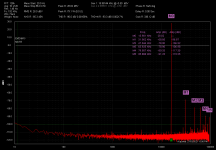 16K THD - 8 ohm load 30 watt.png47.6 KB · Views: 117
 -
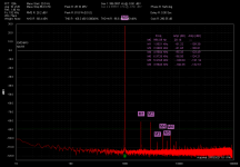 1K THD - 8 ohm load 30 watt.png47.3 KB · Views: 98
 -
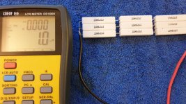 30watt load.jpg114.5 KB · Views: 109
 -
 16K QA401 Loopback Test.png45.8 KB · Views: 113
 -
 1K QA401 Loopback Test.png43.2 KB · Views: 105
To be sure, your persistence and willingness to accept help made this possible. I've seen many give up long before reaching this point... Myself included.
Do you think you can justify tearing the old resistors apart to see what is going on inside?
I sure would like to know of an affordable DAC and/or ADC that gets <0.0002% THD to 20KHz.
But of course there is always Cordell's Distortion Magnifier.
Do you think you can justify tearing the old resistors apart to see what is going on inside?
I sure would like to know of an affordable DAC and/or ADC that gets <0.0002% THD to 20KHz.
But of course there is always Cordell's Distortion Magnifier.
Hi Stuart,
I've just caught up with the last 6 pages as I have been speaker building for the last few weeks.
You have done very well in learning how to test amps etc. Thanks to the guidance from Keantoken and others.
Even though you're a mechanical engineer you have embraced electronics and quickly grasped many amplifier design concepts.
Keep the momentum going!!!
Do you think you can justify tearing the old resistors apart to see what is going on inside?
But of course there is always Cordell's Distortion Magnifier.
I think I can once I find a suitable higher power load resistor that preforms as well the current baseline setup.
Is there a kit somewhere to build bobs distortion magnifier?
Finally... thank you for you kind words of support. It means a lot. There are not many people around in my community that I can talk to about audio amplifier with the knowledge that you possess.
Thanks Harry, I've enjoyed this challenge and bouncing ideas around verbally with you has been one of the most enjoyable parts.Hi Stuart,
I've just caught up with the last 6 pages as I have been speaker building for the last few weeks.
You have done very well in learning how to test amps etc. Thanks to the guidance from Keantoken and others.
Even though you're a mechanical engineer you have embraced electronics and quickly grasped many amplifier design concepts.
Keep the momentum going!!!
")
Thanks Keantoken, I just placed an order. I never knew that this kit was available. Lets hope that they are still processing orders at this time.
Now here is an interesting proposition.
Since we have ruled out that the inductor is the problem, i.e. it is not saturating, and that the culprit is the non-linear load resistor....
Shouldn't measuring at the output of the amp, pre-inductor, be sufficient to determine the amplifier distortion? There are two assumptions here:
- Inductor is linear (which should be unless you have an under-rated one which cannot carry the current without saturating).
- Amplifier R_out << R_load... at 20KHz, this should be the case too.
This would save several hundred $ from not having to get a linear power load resistor like the one Suart showed (I think that one goes for ~ $350... a lot of money a heat dissipator)
Perhaps, but the point of the journey was to understand the where and why of that final bit of distortion. Something I found interesting. Also Stuart's persistence and desire to understand is delightful.
Now, a real speaker load will have its own non-linear frequency behavior of course - I wonder how much impact that has....(just joking)
Now, a real speaker load will have its own non-linear frequency behavior of course - I wonder how much impact that has....(just joking)
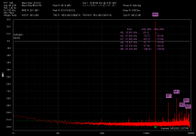
I actually was curious last night and ran a test using a 12uH inductor in series with my baseline 30watt load to see what would happen. As you can see the distortion and harmonics increase significantly. From my final 16khz plot in my last post.Now here is an interesting proposition.
Since we have ruled out that the inductor is the problem, i.e. it is not saturating, and that the culprit is the non-linear load resistor....
Shouldn't measuring at the output of the amp, pre-inductor, be sufficient to determine the amplifier distortion? There are two assumptions here:
- Inductor is linear (which should be unless you have an under-rated one which cannot carry the current without saturating).
- Amplifier R_out << R_load... at 20KHz, this should be the case too.
This would save several hundred $ from not having to get a linear power load resistor like the one Suart showed (I think that one goes for ~ $350... a lot of money a heat dissipator)
So like Sandro said. Maybe to keep a level playing field. Measuring pre zobel network inductor is good enough..
What are your thoughts Keantoken, OS and others?


Hi Johno, the debug experience was definitely great. All I am pointing out is that now that we understand the issue, rather than spend a lot of money on a linear load resistor, I think it is good enough to measure before the inductor.
If you think about it, at $350 for a resistor, might as well buy another HB.
If you think about it, at $350 for a resistor, might as well buy another HB.
Any inductor without an iron etc. core won't saturate.Since we have ruled out that the inductor is the problem, i.e. it is not saturating, and that the culprit is the non-linear load resistor....
Best regards!
Hi Guy's
I just received this from mouser regarding one of there load resistors.
Hi Stuart, Good day!
Thank you for visiting Mouser LiveChat.
Please see below Supplier’s reply reference to your enquiry.
We have carried out an inductance test on the NHS200 8R F.
The results are - Inductance measured at 414 nH (Nano Henrys).
About $80 AUD
284-NHS200-8.0F NHS200 8R0 1% ARCOL / Ohmite | Mouser Australia
Sandro, those are all fair points. I definitely prefer to have a linear load resistor because then the whole setup is more tolerant and it's one less thing to worry about. It is true that almost any amp with a 1.5uH output inductor would have the same result when using that load resistor.
My EBG UXP-300 resistors were gotten on Ebay for a good price. There are plenty of 10ohm versions that are still available but would take some extra work to get to the right value for standard 8/4ohm testing. I was also looking at the Vishay MRA series nonmagnetic wirewound resistors. 10 of the 12W resistors would cost under $80. Still a bit steep, but if you only buy it once, and don't need anything else, then it's probably a good deal. In machining the phrase "buy once cry once" is prevalent. But if this is the only amp Stuart will ever test, maybe it is not so important after all.
The MRA series resistors specify a short term overload rating of 10x power for 5 seconds. 5 seconds is enough time to measure >0.001% THD. So getting 10 MRA series resistors to use as a 300W testing load seems reasonable (submerge them in oil?). But of course with my EBG resistors I don't have to worry about that. And when your tools are reliable and stress free, the cognitive benefits are disproportionate.
It is a good demonstration of theory. Remove the ferrite core and it will not cause much more distortion over the 1.5uH inductor. With a linear load it won't cause any distortion at all.
Since you have remote mounted the inductor, it would be interesting to put it back in place after testing with a linear resistor, and then we will know for sure if any of the nearby steel causes distortion in the inductor. Because we actually can't rule that out unless we have a linear load.
Yesterday I replaced the metal film resistor across the output coil in my bench amp with a nonmagnetic one, removed the magnetic banana jacks and a short steel wire I had used as a bridge on the PCB. Now I can measure at the end of a 35 foot speaker cable with no extra distortion. What this means is that since my computer and ADC are in another room, I don't have to run back to the lab to connect or disconnect the load resistor, I can stay where I am and concentrate on measurements with the load resistor sitting next to me. The less running around and juggling things, the better I can focus and get better results, and reduce the chance of mishaps. And I may never need to buy another set of load resistors.
Also note that my EBG resistors are linear, the distortion I was getting was actually from steel components in the speaker path. Even with a linear load and a relatively small 500nH output inductor, I still didn't get true results unless I connected the load before the output inductor, because of some combination of a steel lytic lead, magnetic Pomona banana jacks, and steel resistor endcaps. I no longer have to worry about any of that, and furthermore my amplifier measures well at the output point, I no longer have to fudge by connecting the load before the inductor.
And that really feels like fudging. I can only imagine Stuart feels the same way if he has been going at this for months to find the solution.
My EBG UXP-300 resistors were gotten on Ebay for a good price. There are plenty of 10ohm versions that are still available but would take some extra work to get to the right value for standard 8/4ohm testing. I was also looking at the Vishay MRA series nonmagnetic wirewound resistors. 10 of the 12W resistors would cost under $80. Still a bit steep, but if you only buy it once, and don't need anything else, then it's probably a good deal. In machining the phrase "buy once cry once" is prevalent. But if this is the only amp Stuart will ever test, maybe it is not so important after all.
The MRA series resistors specify a short term overload rating of 10x power for 5 seconds. 5 seconds is enough time to measure >0.001% THD. So getting 10 MRA series resistors to use as a 300W testing load seems reasonable (submerge them in oil?). But of course with my EBG resistors I don't have to worry about that. And when your tools are reliable and stress free, the cognitive benefits are disproportionate.
I actually was curious last night and ran a test using a 12uH inductor in series with my baseline 30watt load to see what would happen. As you can see the distortion and harmonics increase significantly. From my final 16khz plot in my last post.
It is a good demonstration of theory. Remove the ferrite core and it will not cause much more distortion over the 1.5uH inductor. With a linear load it won't cause any distortion at all.
Since you have remote mounted the inductor, it would be interesting to put it back in place after testing with a linear resistor, and then we will know for sure if any of the nearby steel causes distortion in the inductor. Because we actually can't rule that out unless we have a linear load.
Yesterday I replaced the metal film resistor across the output coil in my bench amp with a nonmagnetic one, removed the magnetic banana jacks and a short steel wire I had used as a bridge on the PCB. Now I can measure at the end of a 35 foot speaker cable with no extra distortion. What this means is that since my computer and ADC are in another room, I don't have to run back to the lab to connect or disconnect the load resistor, I can stay where I am and concentrate on measurements with the load resistor sitting next to me. The less running around and juggling things, the better I can focus and get better results, and reduce the chance of mishaps. And I may never need to buy another set of load resistors.
Also note that my EBG resistors are linear, the distortion I was getting was actually from steel components in the speaker path. Even with a linear load and a relatively small 500nH output inductor, I still didn't get true results unless I connected the load before the output inductor, because of some combination of a steel lytic lead, magnetic Pomona banana jacks, and steel resistor endcaps. I no longer have to worry about any of that, and furthermore my amplifier measures well at the output point, I no longer have to fudge by connecting the load before the inductor.
And that really feels like fudging. I can only imagine Stuart feels the same way if he has been going at this for months to find the solution.
The results are - Inductance measured at 414 nH (Nano Henrys).
About $80 AUD
284-NHS200-8.0F NHS200 8R0 1% ARCOL / Ohmite | Mouser Australia
It's a better cost to power ratio than the Vishay MRAs. 414nH is still 1/3rd the value of your output inductor. Can you ask them to see if the resistor is magnetic? If it was inductive, but not magnetic, then it would still be a linear wirewound resistor. I can only assume it has steel parts if they do not claim nonmagnetic in the datasheet.
- Home
- Amplifiers
- Solid State
- diyAB Amp - The "Honey Badger"