Your general reasoning does not apply.
Bobellis gave you the clue
Bobellis gave you the clue
A capacitor cannot be a snubber. It's resistance that absorbs/dissipates the energy.I'm not a fan of snubber caps, they have the potential to do more harm than good .............
Just to clarify: these 10nF caps not shown were intended for bridges. Most likely I'll not add them as soldering them to bridges makes further connections more difficult.
OK, adding randomly caps to PS electros may make things worse but as a concept it works. Combinations of these additional caps in PSs are described in most books including the most recent one by Bob Cordell.
I have a friend who is electronics engineer and has or rather had his own business as he retired recently. He made and repaired some equipment for merchant navy. When I was building one of my amps in quite distant past I dug out one of Otala's papers on PS and how to make these better. So I asked a friend of mine for assistance. First, he checked signal attenuation pattern of my electros (as frequency rises attenuation falls and then rises) then adding caps one can keep it falling into a few MHz.
Anyway, having selected a few caps from the first test and having connected my base PS to my new amp he started to add these just a few different cap to see their impact. First, without audio signal and then with 10kHz signal into a LRC load. There was one particular 100uF cap he was using in his HF equipment, which had positive smoothing effect in combination with my amp and PS electros. Adding about 1uF poly and about 1ohm resistor to the board where PS was connected also had some effect. I do not remember exact R-C values as this was long time ago.
Later I kept adding that 100uF cap to PS and RC combination to the board without checking. I do not know if it was improving something or making it worse.
These 1uF caps I sketched in my intended PS I copied from Bob Cordell's book. Most likely these are not universal values for all kinds of electros but if Bob showed these in his book he must have had some grounds for doing that.
From that past experiment it was that particular special 100uF cap designed for HF plus RC on board which worked with my electros and my old amp. If one could hear that improvement I do not know. So maybe when building amps at home choosing the simplest solutions has its merits and certainly saves time and reduces costs a little bit.
cheers,
Could you give references and I will read what he actually says?..........these additional caps in PSs are described in most books including the most recent one by Bob Cordell..........,
Could you give references and I will read what he actually says?
Designing Power Amplifiers - chapter 16: Power Supplies.
cheers,
I disagree with your reading and with Cordell's use of the word "can".
see fig16.7 and fig16.9.
refer to section 16.3 Bypasses and Snubbers for Reservoir Capacitors
referring to fig16.7 Cordell says
"The most common approach is to bypass the reservoir capacitors with with a quality film capacitor".
Then adds
"Even with a bypass capacitor in place there often remains the possibility of ...... component inductances that can form tank circuits......."
In the next paragraph he adds
"For this reason a high frequency snubber circuit can be added ....."
"This snubber will not do much for the 1MHz resonance"
It's the use of "can" in that sentence that I consider quite misleading.
I would suggest the least change would be: For this reason a high frequency snubber circuit should be added.
But better still, would be to state:
Instead of adding the usual film cap, it is better to add a snubber to damp the high frequency resonances.
i.e. I contend that adding the quality 1uF film cap is wrong, in that it tends to promote the ringing and does NOT help with reducing the supply impedance at all frequencies. Note Cordell tells us that impedance has doubled to 0.3ohm.
If you now refer to fig16.9, you will see that Cordell has removed the 1uF film cap and replaced it with snubbers across the diodes.
Even simpler is to place a single snubber across the secondary.
Last edited:
Interesting conversation regarding PS snubber/bypass circuits. As not having the
electronic background as obviously others have, I intend to keep my PS simply
basic to start with. Xform, bridge, caps, then straight to the amps. Am I on
the right track here? Or should I be leaning toward a more complex design?
I am constructing my own chassis/case from 0.125" aluminum, it involves quite a lot of cutting and drilling, thus creating swarf and debris. Obviously this is electrically
conductive so needless to say to avoid cross contamination. I am a mere mortal
that only has one workshop, therefore mechanical and electrical work are never mixed. On the subject of cases, where can I source a insulated RCA connector for
the input that has threads long enough to span my 0.125" back panel? The standard
types I have are a little too short when you include the insulators.
..............
Even simpler is to place a single snubber across the secondary.
You already have my preference !............. what about putting RC snubbers (100nF 1ohm) across each secondary winding? ..........,
1ohm may not be correct !!!!!
and 100nF may not be correct. I see that you like to keep it simple and it's usually the safest way.
Anyway, for those interested in experimenting there is a paper by Jim Hagerman about Calculating Optimum Snubbers. Apparently, calculated values do not require any further tweaking. However, soldering optimum snubber circuits (RC||C) to bridges is pretty inconvenient so keeping it simple is in a way enforced unless one wants to experiment with such circuits within PS.
Out of memory RC circuits I used to place on board was 1 ohm and about 0.5uF from ground to V+ and V- but these values were tested on a particular PS and amp. As I do not have these very low ESL (and ESR) 100uF/100V caps anymore I'll have to keep it simple - and I do not have a scope at home (yet).
cheers,
http://www.cde.com/tech/design.pdf
Snubber Circuits Suppress Voltage Transient Spikes in Multiple Output DC-DC Flyback Converter Power Supplies - Tutorial - Maxim
These examples are more SMPS related. I just disassembled a sub amp
(linear) , it just had .01uF/400v across each diode in the bridge(s).
Can we argue with an OEM ? Yes .... but it (the PS) functioned .
OS
Success at last
Well my persistence finally paid off. Today I had the chance to work on my bad channel. Replaced D1,D2,R4, and Q15(not sure that I needed to but measured funny). Powered up and presto clean music through my test speakers. Now all I need to do is reassemble the amp chassis burn it in for a while and give it a serious listen on some good speakers.
PJN
That's good news. Congratulations!
cheers,
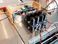
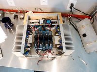
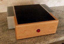
I finally finished everything up and had a quick listen on some decent speakers. Kudos to Ostripper, it is a very powerful, clean, neutral, and dynamic amp. The imaging is outstanding. When folks say that this amp has a grip on speakers they're not kidding. I'm going to let it burn in for some hours and maybe do a comparison to my SKA and F5 in my main system over the holiday break. I've included some build pics, my version uses 63 VDC rails in dual mono configuration, the only downside is that this monster weighs about 50 lbs.
PJN
PJN
Attachments
Nice combo...
True DIY , I like the wood/aluminum "merger".
The imaging you hear is the excellent PSRR of the blameless topology.
You would hear this even if you were not true dual mono.
Badger damping factor is above 150 , speaker cable is the weak link.
I'm going to add one of these to my badger (below1 - pga2311) , so I can sit on
my ar$e and do the memorex thing (below 2) (hair blowin' in my chair).
PS - I see resistors on your PS boards ... are you doing CRC ?
OS
Attachments

Last edited:
Hi Guys,
The transformers are Antek AS3445 (300VA). Each is good for 6.6 amps each for a total of 13.2 amps for this build. For comparison the AN8445 is good for 8.9 amps. The PSUs are the DIY store boards and are set up as CRC. Really nice boards by the way. I picked up a 1/8" aluminum plate for $40 on flea bay, and I had some maple laying around that I used for the front. The heat sinks are 5" high and 10" long from Heat Sink USA. The case dimensions are about 5" high, 17 inchs wide at the heat sinks (2 1/2" high), and about 14 inches deep. The sinks barely get warm after loud volume for an hour. That memorex add was the first thing that came to mind, this amp can really blow your hair back.
PJN
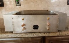
Another Honey Badger is alive. Built with OS's Mouser BOM, I used MPSA-18s for the input pair, MJE15034/5 and NJW0281/0302. Input pair Hfe = 580 left and 579 right, exact match for each pair according to my cheap meter, less than 1mv offset on initial power up. Following the build guide, power up went smoothly, the only nerve wracking part was bringing the bias up. I was surprised how many turns it took to get the bias to start.
I haven't had a chance to do any critical listening yet, so no comment. Eventually want to do a Leach/Honey Badger shoot out. 5 pair Leach biased at 50 mA/device vs. 100 mA/device Honey Badger.
I'm still working up a design to send to Front Panel Express for this and the Leach below it. Source is an Oppo BDP-103 feeding the amps directly.
Attachments
- Home
- Amplifiers
- Solid State
- diyAB Amp The "Honey Badger" build thread