Hi Guys,
I had the chance to try my amp boards again, I used a bulb tested to power up, and lowered the bias to 20 MV, offset 0 vdc, and loweres the CSS voltage across R14 to 8 vdc. Then removed the 10 R resistors across F1/F2, installed fuses and powered up without the bulb tester. Bias held at 20 MV and everything looked good, but after ~ 2 min something crapped out, fuses blew. I checked everything on the board, all diode are good, all resistors good & correct values, I can only think that I had some damaged/stressed transistors from my earlier missteps that blew. I'm going to replace all of the transistors and try again. I can only hope that my persistance will pay off.
PJN
Hi Nissman,
I got everything from Digikey, and they looked legit. I
I think that getting and installing the wrong resistors, and making the mistake of installing the wrong transistor for Q15(really small lettering and inattention) cost me. It's been a learning experience.
PJN
I got everything from Digikey, and they looked legit. I
I think that getting and installing the wrong resistors, and making the mistake of installing the wrong transistor for Q15(really small lettering and inattention) cost me. It's been a learning experience.
PJN
Damaged parts can play havock. Just going through my notes on lateral mosfet amps I found a more puzzling case. One of our members built two identical amp modules, one worked perfectly well, the other did not even when power transistors were swept. So he sent back transistors (Exicons) in question to Profusion. They did their checking and did not find anything wrong with these but refunded him for those in question. In the end appeared that one of these transistors had a fault which appeared only at full working conditions with longer lead connections. Once he got good transistors both modules worked perfectly well.
Even Bob Cordell and Nelson Pass were straining their brains on the problem but rightly suggestes some faulty part/s - but which one was the question as Profusion tested all the transistors in question and they were good but one was not good enough.
cheers,
Even Bob Cordell and Nelson Pass were straining their brains on the problem but rightly suggestes some faulty part/s - but which one was the question as Profusion tested all the transistors in question and they were good but one was not good enough.
cheers,
Last edited:
Hi Guys,
My persistence has only half paid off, but still it's progress. I stripped all of the transistors out of both boards and replaced with new transistors, the new transistors were tested with the diode function on my DMM before and directly after they were installed. Powered both boards up with a light bulb tester and 10R resistors across F1 & F2. Set initial settings, DC offset ~ 0, bias ~ 25 mV, CCS ~ 7 vdc across R14. Removed 10 R resistors, installed fuses powered up with full power finalized settings DC offset ~ 0, Bias – 44 mV, CCS – 8.25 vdc across R14, and let each amp run for 15 minutes to settle. All readings held steady on both amp boards. Assembled amp fired it up one channel working is fine, but the other just puts out a low hum. No fuses blew and power LEDs for bad channel were lit. Pulled out bad channel and started checking things. While checking for shorts I did notice that the input ground read 15R on the bad amp but read nothing on the good amp, also the input + on the bad amp reads nothing, but reads 5 R on the good amp. No shorts between heat sinks and transistors. All resistors and diodes checked out fine, but couldn’t get decent reading on D1/D2 because they’re on a common pad. Below are the transistor readings for the bad channel. Since I’m not reading 5R on the + input on the bad amp I’m suspecting that D1/D2 may be damaged.
Q Readings on new transistors
B-C B-E C-E
1 0.880 0.880 1
2 0.880 0.880 1
3 0.819 0.823 1
4 0.819 0.823 1
5 0.796 0.801 1
6 0.796 0.801 1
7 0.819 0.823 1
8 0.819 0.823 1
9 0.796 0.801 1
10 0.789 0.793 1
11 0.784 0.788 1
12 0.784 0.788 1
13 0.767 0.771 1
14 0.708 0.715 1
15 0.730 0.733 1
16 0.662 0.668 1
17 0.662 0.668 1
18 0.662 0.668 1
19 0.673 0.677 1
20 0.673 0.677 1
21 0.673 0.677 1
After installation.
B-C B-E C-E
1 0.853 0.851 1
2 0.853 0.851 1
3 0.810 0.813 0.849
4 0.811 0.814 1
5 0.777 0.782 1
6 0 0.743 0.743
7 0.811 0.814 1
8 0.767 0.270 0.890
9 0.794 0.800 1
10 0.685 0.675 1
11 0.681 0.167 0.817
12 0.768 0.772 1
13 0.674 0.626 1.346
14 0.694 0.703 1
15 0.731 0.735 1
16 0.621 0.628 1
17 0.622 0.630 1
18 0.624 0.632 1
19 0.602 0.612 0.920
20 0.607 0.618 0.917
21 0.611 0.620 0.920
After trial
B-C B-E C-E
1 0.882 0.823 1 Ok
2 0.802 0.804 1 Ok
3 0.802 0.805 1 Ok
4 0.802 0.805 1 Ok
5 0.793 0.796 1.134* is different than before test, not sure if blown
6 0 1 1 looks blown
7 0.802 0.805 1 Ok
8 0.760 0.260 0.876 Ok
9 0.801 0.805 1 Ok
10 0.701 0.693 1 Ok
11 0.695 0.167 0.804 Ok
12 0.765 0.768 1.260* is different than before test, not sure if blown
13 0.679 0.627 1.076* is different than before test, not sure if blown
14 0.713 0.722 1 Ok
15 0.738 0.740 0.684* is different than before test, not sure if blown
16 0.620 0.627 1 Ok
17 0.619 0.627 1 Ok
18 0.619 0.627 1 Ok
19 0.606 0.616 0.936 Ok
20 0.606 0.616 0.935 Ok
21 0.609 0.616 0.935 Ok
Note on Q3 : C-E installed on good board was 0.849, when removed Q3 C-E measured 1, installed a new one which also measured C-E = 0.849, this was different from the C-E = 1 on bad board.
Next steps : Measure all transistors on working amp board to help pinpoint any bad ones on “bad” board, replace D1/D2, replace Q6, Q5, Q15, and check bottom of board again under magnification for and solder bridges, ect.
If anyone has any ideas where I should look next please let me know.
Thanks,
PJN
Hi PJN, I started writing this post before your latest post but will continue. I have to admit to being a bit pedantic re descriptions of test procedures; but fixing problems demands rigor.
"read nothing on the good amp" presumably means you read zero ohms/short circuit?
"+ input" means the "hot" (ungrounded) side of the input?
If this is so you should be seeing 100K between input hot and input ground. As we have a blocking capacitor C1 there will be nothing shunting R1.
Are you using RCA Phono sockets on the inputs? If so, they should have "oversized" holes in the panel so that the outer shells are insulated from the panel irrespective of whether there is a plug inserted or not. This remark applies more to RCA connector strips mounted from behind the panel. Maybe, in you case, you are using surface mounted sockets that come with insulating bushes. If the RCA sockets are not insulated R4, D1, D2 will be shorted and thus not perform their intended function.
I worry about the remark that input ground read "nothing" on the good amp.
You need to resist the temptation to perform wholesale removal of parts from the board as these operations take a toll on the board plus you get a second opportunity to make mistakes when replacing them. If you are seeing very little DC offset at the outputs this is good news, telling you that you probably have no faulty transistors.
Check out your input connections.
As for your latest post, R4 being destroyed tells us that it is not being shorted by the input connector outer shell, but is not good news, suggesting that you may have instability problems.
Do you have an oscilloscope?
Don't connect any output load, particularly valued speakers to the amp untill this issue is sorted out. One crude indicator of instability is to take note of the output Zobel resistor R50. Is it getting very hot or is it burning up. Be carefull that you have input and output wiring well separated, particularly if using temporary clip leads for testing.
Keith
If you have installed all new and tested transistors and some blew then some other part/s is/are also faulty. Hopefully, fault does not manifest itself only under working conditions so check other parts, especially in the circuit of Q12,13 and 15 as these may be damaged as well. There should be almost no current across R4. D1 and D2 are protection so the same thing happens when large current flows between small signal ground and the amp's ground. It may result from other faulty components and/or oscillation.
cheers,
PS I've just noticed on the v2.4 circuit diagram that the nfb returns to the amps ground and not to the signal ground, which is a drawing error I suspect.
cheers,
PS I've just noticed on the v2.4 circuit diagram that the nfb returns to the amps ground and not to the signal ground, which is a drawing error I suspect.
Last edited:
Hi Keith,
I was incorrect when I stated
" While checking for shorts I did notice that the input ground read 15R on the bad amp but read nothing on the good amp, also the input + on the bad amp reads nothing, but reads 5 R on the good amp." I double checked it is the ground input to the amp (-) reads 5R, the hot input (+) reads nothing on the good amp, I was pretty tired at the time from screwing around with the bad amp board.
I'm using panel mounted RCAs for the inputs they are well insulated and I had double checked them to make sure that there were no shorts after mounting.
I've replaces D1 & D2, they did appear damaged, the diode function on the DMM meter reads ~ 0.880 on new ones but only 0.25 on the ones that I removed. I'm waiting for some replacements for R4 to arrive now.
R4 burned after the board was powered up and I was screwing with the inputs trying to hook up up a source, so I could have inadvertently shorted something. Since all I have is a DMM my plan is to replace R4, go over the bad board with a fine toothed comb, check everything twice, and replace any components that don't read the same as when I has originally installed them, Q15 comes to mind. Then I'll try again with the light bulb tester.
PJN
PS for HB
Hi,
I've just collected all parts for my Honey Badger modules except for toroids. As the system will be active with active sub with diaphram control, I need
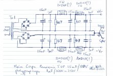
2x2 Badger modules to drive bass drivers from 60-80Hz to 600-800Hz and mid-high systems from 600-800Hz uo to 30kHz or so. Mid-high crosover is passive. Each HB dual module will have its own PS and will be driving Left or Right channels. Diagram of my main PS is attached.
First question is the choice of resistors for CRC filters and dreaining resistors. Initial values are shown. Any other corrections/suggestions?
Secondly I have to buy two toroids. The choice is between 625VA and 800VA and 2x41.5V and 2x46.5V. The cheapest, currently on special, is 625VA 2x46.5V and I thought about going for this one as I'll be driving an active system. What do you think?
cheers,
PS nominal voltages are 2x40 and 2x45V on 230V mains but we have 240V mains so actual voltages will be somewhat higher.
PS 2 I may also go for a regulated PS for IS-VAS by adding 2x12V toroid and about 2x70V PS
Hi,
I've just collected all parts for my Honey Badger modules except for toroids. As the system will be active with active sub with diaphram control, I need
2x2 Badger modules to drive bass drivers from 60-80Hz to 600-800Hz and mid-high systems from 600-800Hz uo to 30kHz or so. Mid-high crosover is passive. Each HB dual module will have its own PS and will be driving Left or Right channels. Diagram of my main PS is attached.
First question is the choice of resistors for CRC filters and dreaining resistors. Initial values are shown. Any other corrections/suggestions?
Secondly I have to buy two toroids. The choice is between 625VA and 800VA and 2x41.5V and 2x46.5V. The cheapest, currently on special, is 625VA 2x46.5V and I thought about going for this one as I'll be driving an active system. What do you think?
cheers,
PS nominal voltages are 2x40 and 2x45V on 230V mains but we have 240V mains so actual voltages will be somewhat higher.
PS 2 I may also go for a regulated PS for IS-VAS by adding 2x12V toroid and about 2x70V PS
Last edited:
Janusz,
Any of your transformer options will work. I'd go for the ones on sale. If the load is 4 ohms or less you should run through Safe Operating Area calculations, especially if you are using NJW outputs. You're only looking at the difference between 68V and 61V rails, but it might matter for the smaller NJW devices.
Bleeder resistors are just a tradeoff between how fast do you want the filter capacitors to drain and how much power do you want to waste during normal operation. Your 4K7 is a reasonable value. If you are using speaker protection board, you might want to consider piggybacking a NC relay to disconnect the bleeder resistors from ground when the amp is inactive. Then you can use lower value bleeders without having to worry about the dissipation during normal operation.
You might consider more parallel resistors in the CRC section. Again it's a tradeoff, this time between ripple reduction and dissipation/voltage drop. I used Nelson Pass' F5T supply as a guide for the net R value, he uses 7 0R47 in parallel IIRC. The losses are particularly significant in a class AB amp as the signal ends up changing the rail voltage. If the R value is too high you might have ripple that exceeds the amp's PSRR ability. An argument for separately regulated front end supplies.")
I'm not a fan of snubber caps, they have the potential to do more harm than good and require advanced measurement capabilities to get them right. YMMV of course. They are also more effective at the amp board where OS has given us room to put some nice electrolytics and a film bypass.
Happy building. My HB is still partially assembled on my kitchen table. Maybe this weekend...
Any of your transformer options will work. I'd go for the ones on sale. If the load is 4 ohms or less you should run through Safe Operating Area calculations, especially if you are using NJW outputs. You're only looking at the difference between 68V and 61V rails, but it might matter for the smaller NJW devices.
Bleeder resistors are just a tradeoff between how fast do you want the filter capacitors to drain and how much power do you want to waste during normal operation. Your 4K7 is a reasonable value. If you are using speaker protection board, you might want to consider piggybacking a NC relay to disconnect the bleeder resistors from ground when the amp is inactive. Then you can use lower value bleeders without having to worry about the dissipation during normal operation.
You might consider more parallel resistors in the CRC section. Again it's a tradeoff, this time between ripple reduction and dissipation/voltage drop. I used Nelson Pass' F5T supply as a guide for the net R value, he uses 7 0R47 in parallel IIRC. The losses are particularly significant in a class AB amp as the signal ends up changing the rail voltage. If the R value is too high you might have ripple that exceeds the amp's PSRR ability. An argument for separately regulated front end supplies.
I'm not a fan of snubber caps, they have the potential to do more harm than good and require advanced measurement capabilities to get them right. YMMV of course. They are also more effective at the amp board where OS has given us room to put some nice electrolytics and a film bypass.
Happy building. My HB is still partially assembled on my kitchen table. Maybe this weekend...
Thanks Bob,
Could you give me a link to Nelson Pass' F5T PS?
I found a number of threds on the amp and schematics but as some threads have thousands of posts finding something in them is not easy.
It would be nice to know corner frequency of used caps for given resistance or impedance for given frequency. Unfortunately in my notes I do not have the formula. I know it's beter to have it smaller than too high.
OK, I'll go for 2 x 625VA 2 x 46.5V then. It's the cheapest of all. Higher PS voltage will give better headroom for transients.
I'll be using transistors from my supply box collected over years. Output: mg6331/9411. Drivers as suggested mje15032-33. Other small changes will be q1,2 = ss9014d rather than c so R15-16 will be 150ohm and R20-21=150; Q3,4 = 2n5551; Q5,6 = BC560c; q9=2sa970bl; q8=ksc1815; q7=2n5551 or 2sc2240bl; q10=2sa1406e or 2sa1209e; q11,12=2sc2911e; q13=2sc3117s. Zener probably 18V with higher PS. R24=1k; c7=82pF, c8=390pF.
I might go for front end regulated PS. I'm going to order some boards to be made in China but I won't have these before February-March next year (pcb design still needs some work) so HB will have to work without these for a few monts or longer...
Good luck with your HB, looks you will have it completed very soon. If I manage to have my first pair running by the end of the year I'll be happy but most likely it'll be next year.
cheers,
Last edited:
I'll go further................
I'm not a fan of snubber caps, they have the potential to do more harm than good .............
Remove the four 1uF capacitors.
http://www.firstwatt.com/pdf/art_f5_turbo.pdf
That's a problem with bachelorhood - there's nobody to push me to get it off the table. Boards are assembled to the heat sinks, PSU boards built, I just need to mount them into the case and wire it up. You'd think I could find a couple hours to get it completed, but I am having other kinds of fun.
That's a problem with bachelorhood - there's nobody to push me to get it off the table. Boards are assembled to the heat sinks, PSU boards built, I just need to mount them into the case and wire it up. You'd think I could find a couple hours to get it completed, but I am having other kinds of fun.
Thanks Bob. Take your time, life without fun is not worth much.
Andrew T, could you please explain why?
General reason for having these is that big electros are not so good at higher frequencies so adding 1uF plus high quality polypropylene cap provides additional filtering and impedance continues to fall with frequency. One may add additional high frequency RC snuber in parallel to combat potential impedance peaks due to wiring. Sometimes it's worth adding 100uF low ESR cap in parallel. That helps dumping HF resonances. I did it a few times in the past.
cheers,
- Home
- Amplifiers
- Solid State
- diyAB Amp The "Honey Badger" build thread