Thanks for the comments on Q9 and TMC and info on transistors. I have about 100 of 2sa970bl and no ksa992.
Yesterday, Mouser Australia had only N and P pairs for NJW, Toshiba and Fairchild. I did not check MJL4xxx. I have 8 or 10 pairs at home but it has worse linearity so it's not my favorite. Unfortunately, only one channel was available for MJL3xxx, MJWxxx.
I considered Toshiba/Fairchild as these are TO-264 so have larger contact area. However, fairchild 2sc5200 has better linearity than Toshiba while Toshiba 2sa1943 has it better than fairchild. At lest that's what datasheets show. So matching two different manufacturers theoretically makes sense here. Mixing these within the same channel could crerate problems and would require larger emitter resistors.
Talking about resistors I'll use 0.1ohm non-inductive as I'm going to get best matches from batches of 25pcs for each channel. With not so well matched laterals i always used 0.1 or 0.15 and with matched bjts as well. As R49 i'll use no more than 1.5-2.2 ohms (5W). Less ringing. R2 will also be small, maximum 220 so C2 will be larger.
Another change I'm going to make is gain. Most my amps have it set at 28 so I can mix them in my active systems. It's also some precaution as I have a teenager at home. Gain over 40 is huge as most preamps can deliver at least 2.5V and most well over 5V - especially if driven from CD/SACD players.
cheers,
Dropping the value of the emitter resistors might also affect thermal stability. you might have to tweak the vbe. I can't advise on this since I've never used .1 for Re.
R3 + R6 =33k and R5 + R2 = 820R .... the gain - drop the 33k's to 27k , any further decrease will affect TMC and the unity phase margin (I simulated). Raise the 820R's to either 1.2K or 1.5K , this will result in a gain of 30 and 24.
With these values all other spec's will be the same. Enjoy!
OS
Last edited:
PA rules and questions
Thanks for suggestions Ostripper. True, reducing emitter resistor values affects thermal stability but also reduces distortion. I usually solder in 0.22 and then on the other side of the board add larger 1W-2w resistors to see wtat is thermally happenning.
When it comes to laterals I saw amps without any such resistors but I always used 0.1 or .15.
The other part of what you have said: R3 should equal R6 to minimize offset. That is clear for me, while at the same time R5 should not be too small. R2 and R5 values should not be too high for noise reasons.
I have never built amp with TMC. In his book Bob describes how it works but does not explain how it's RC values should be selected in relation to nfb resistor and gain values. I'm guessing that R6 should be much larger than R24 (caps values are dependent on R24 and the larger cap should be at least 5x larger than the smaller one). So what is the safe R6/R24 ratio range??? As a rule of a thumb?
cheers,
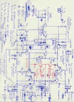
PS one of my first amp designs and example of calcs as a souvenir from old times and some rules (it would be nice to see calcs of this kind in PA design books):
Isource = (2…5) * IRbmaxT6;
IRbmaxT6 = Imax / (h12Tdriver*h12Toutput);
h21 of the output driver can be measured: assume the worst scenario of 20 for 3055 or a better K503;
h21 of the driver can be measured: h21=80:
Isource = (2…5) * 4.5A / (20 * 80) = (2…5) * 3.5A / 1600 = 5.5 … 14mA
Assume Isource = 10mA;
Thanks for suggestions Ostripper. True, reducing emitter resistor values affects thermal stability but also reduces distortion. I usually solder in 0.22 and then on the other side of the board add larger 1W-2w resistors to see wtat is thermally happenning.
When it comes to laterals I saw amps without any such resistors but I always used 0.1 or .15.
The other part of what you have said: R3 should equal R6 to minimize offset. That is clear for me, while at the same time R5 should not be too small. R2 and R5 values should not be too high for noise reasons.
I have never built amp with TMC. In his book Bob describes how it works but does not explain how it's RC values should be selected in relation to nfb resistor and gain values. I'm guessing that R6 should be much larger than R24 (caps values are dependent on R24 and the larger cap should be at least 5x larger than the smaller one). So what is the safe R6/R24 ratio range??? As a rule of a thumb?
cheers,
PS one of my first amp designs and example of calcs as a souvenir from old times and some rules (it would be nice to see calcs of this kind in PA design books):
Isource = (2…5) * IRbmaxT6;
IRbmaxT6 = Imax / (h12Tdriver*h12Toutput);
h21 of the output driver can be measured: assume the worst scenario of 20 for 3055 or a better K503;
h21 of the driver can be measured: h21=80:
Isource = (2…5) * 4.5A / (20 * 80) = (2…5) * 3.5A / 1600 = 5.5 … 14mA
Assume Isource = 10mA;
Attachments
So what is the safe R6/R24 ratio range??? As a rule of a thumb?
I've both simulated and built the R24 value at anywhere between 470R-1k.
I also have built badger - like amps with gains of 24-40 (R6/3 = 22k - 33k).
All these combo's fall within the 88 - 90 degree UG phase margin (won't oscillate). What does change is the unity gain freq. , the slew rate is affected slightly , and as you said .. the noise will increase with larger R5/2 values.
Play around , these changes will NOT "break the bank" and may even improve on things. In that case , report back with any findings !
BTW - you can also build this amp without the cascode or even without the mirrors (that's going to far). Miller compensation can be TMC or regular single 68pf C7 (jumper C8/omit R24). Also 4 ways to reference the cascode (C/R/Z).
C18/19 are there (option) to allow the "brutal shunt" (now being discussed in bob's thread) for the EF2 drivers. Even try the "LC" (lead compensation)option. You seem most knowledgeable and these techniques
should present little difficulty.

OS
Janusz, the reason you often see laterals without emitter resistors is that at high currents they tend to be self limiting. Also the on resistance is high enough that they generally won't go too crazy.
BJTs and verticals on the other hand want to run away with temperature increases, and need some form of compensation. I haven't had the nerve to run lower than 0R22 (in a Leach amp which is overcompensated anyway).
OS, How about losing the mirrors and keeping the cascode? I think I remember reading that Professor Leach tried mirrors and thought his amp sounded better with a resistor load on the inputs. A little lower open loop gain. I may have to build a few Badgers to test that idea...
Would this work for the zener diode in the cascode/current mirror?
BZX85C15 Fairchild Semiconductor | Mouser
BZX85C15 Fairchild Semiconductor | Mouser
OS, How about losing the mirrors and keeping the cascode? I think I remember reading that Professor Leach tried mirrors and thought his amp sounded better with a resistor load on the inputs. A little lower open loop gain. I may have to build a few Badgers to test that idea...
That is also possible. You lose about as much OLG as using FET input devices.
degenerate the input pair with 22R-33R , that brings things back to normal.
A dual mono setup would be the best test bed for these mods as you would have poorer PSRR. My subwoofer Badger might be like this. Jumper C-E of Q3-6 (omit) , R20-21= 1.2-1.5K and R15-16 = 22-33R ,
Q1-2 would have to be higher Vceo ....
- ksc1845 (swapped b-e)
- ZTX653 (EBC)
- or higher gain ZTX694B (EBC - another good sub even for a "complete" badger)
http://www.mouser.com/ds/2/115/ZTX694B-92739.pdf
.... all would work well.
Critical listening would be the only way to tell if they "sounded" better ??
OS
Last edited:
Would this work for the zener diode in the cascode/current mirror?
BZX85C15 Fairchild Semiconductor | Mouser
Yes. (12-24V / 250mw+)
OS
Janusz, the reason you often see laterals without emitter resistors is that at high currents they tend to be self limiting. Also the on resistance is high enough that they generally won't go too crazy.
BJTs and verticals on the other hand want to run away with temperature increases, and need some form of compensation. I haven't had the nerve to run lower than 0R22 (in a Leach amp which is overcompensated anyway).
OS, How about losing the mirrors and keeping the cascode? I think I remember reading that Professor Leach tried mirrors and thought his amp sounded better with a resistor load on the inputs. A little lower open loop gain. I may have to build a few Badgers to test that idea...
That's one of the reasons I fell for laterals. The other was their sound. In those times power bjts were nothing to brag about. When I built my first PA with laterals (ETI500 kit which I have moded many times) in 1984-85 I was rally surprised. All my friends were surprised. Much more detailed sound and quite different.
thanks ostripper for advice.
When it comes to LTP one could make it as fast as it goes using Stochino's approach. No Q3-4, higher current to mirrors (R20-21 = 5-10ohm) and anti saturation diodes.
cheers,
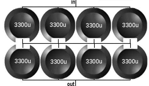
OS, you used the v20 DIYAudio PSU boards, right? What caps did you use?
No,I have (made) my own PSU boards. One has 4 X 6800uf nichicon 80v (single amp) the other (in my stereo amp) has 4 X 8200uf 100v apex audio samwha caps.
Both have 25A 400v bridge's.
OS
I posted this on the PSU thread too-
OK, onto the caps
The Honey Badger guide recommends 40,000uf per rail. These are the only ones I can find that fit, right lead spacing, etc.
LLS1K103MELC Nichicon | Mouser
Now these (LKS1K103MESC Nichicon | Mouser) are what I'd like, as they claim to be "audio grade" and are only a few bucks more but I can't find them anywhere.
Any other suggestions?
See the other thread. http://www.diyaudio.com/forums/diya...power-supply-circuit-board-2.html#post3590940
Last edited:
Has anyone given any thought to installing external gain controls
to allow the amp to be "matched" with others (bi-amping etc)?
NE5532 Low Pass Filter Subwoofer Process Circuit Frequency Volume for Amplifer | eBay
Not only gain , but this nice PCB could be low , high , or all pass with minor mods. (Sub - HPF for a 2.1 system). Unity gain or X2 gain on the second op-amp could also be done. Socketed IC's are nice , too.
(photo below). Just $8usd
The circuit is common on the internet (2'nd photo) comes with the dc supply.
A real deal.
OS
Attachments
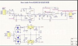
Just a caution with that circuit. The input mixer feeds the positive inputs that circuit would cause a fair amount of crosstalk. Although it makes the filter harder to incorporate, it should feed the negative input to avoid crosstalk. I'd use a buffer of some sort between the main signals and that board if I was using the mixer option.
I used Rod Elliot's Project 38 with the same input to switch on my amp and was surprised how much crosstalk there was, even when I increased the mixer resistors from 10K to 200K. I ended up just using a channel signal.
I used Rod Elliot's Project 38 with the same input to switch on my amp and was surprised how much crosstalk there was, even when I increased the mixer resistors from 10K to 200K. I ended up just using a channel signal.
Just a caution with that circuit. The input mixer feeds the positive inputs that circuit would cause a fair amount of crosstalk. Although it makes the filter harder to incorporate, it should feed the negative input to avoid crosstalk. I'd use a buffer of some sort between the main signals and that board if I was using the mixer option.
I used Rod Elliot's Project 38 with the same input to switch on my amp and was surprised how much crosstalk there was, even when I increased the mixer resistors from 10K to 200K. I ended up just using a channel signal.
I'll be using a separate sub out from my sound card.I will use 2 in mono for my HPF's (all will be mono for 25$), thank's for pointing out this shortcoming .
OS
Define the audio band? Does that include the bass?
Isn't there a knob missing?
Volume and bass are a good start; however, what about low frequency limit, just in case we'd like dramatic distortion reduction while also increasing available bass power and SPL capacity? Line level filters: Greg Ball: BassXt AND Bob Cordell: EQSS
This sort of thing looks very useful for decreasing X-MAX (speaker bang!) events from high power subwoofer amplifiers.
Or for full bandwidth amp. . .
However, at my house, the coupling caps, including speaker negative are tuned:
Input, highest
NFB-shunt cap, middle
Output, lowest
Yes, a bit spendy and bulky.
And while this does not include a bass boost, it also does not amplify an op-amp effects box. So there is that difference. Instead, with just the passive parts, tuned to support a specific speaker, the system has more bass capacity. The speaker cones spend less time flailing haplessly distorting and more time making low clear bass. No op-amp needed.
Personally, I find that the caps thing is something I can actually manage to do--although it is costly, it is also really easy.
P.S.
Either BassXT or EQSS may be combined in addition to the old school caps method, for use with sealed box subwoofer.
And, with that much capacity, an ultrabass box might be enjoyable for more "hearable" bass, since it is played as fundament but we hear as harmonic.
And, if the amplifier is a lot more powerful than the subwoofer, it is possible to replace the feedback-shunt resistor with a multi-turn potentiometer of similar value, connect inversely parallel diodes clipper to pot wiper and then connect diodes to positive input. . . so you can turn the dial to a position where the voice coil won't strike the magnet (or at least decrease the occurrence). Perhaps that circuit also protects the amp a bit, if in case the LTP is caused to clip before the outputs could.
Last edited:
As it was conceived - link to postThe build guide lists D8 and D9 as optional but doesn't explain what they do. I don't see them on the schematic either. Do I need them?
http://www.diyaudio.com/forums/solid-state/192431-diyab-amp-honey-badger-11.html#post2643875
OS
- Home
- Amplifiers
- Solid State
- diyAB Amp The "Honey Badger" build thread