If anything - with ON semi driver/output devices and the MJE340 for the thermal
feedback , the Badger should be negative co-efficient.
I ran one (a badger) on a tiny heatsink , it went into class B before it fried eggs !")
But , running idle .... it should stabilize even if on an insufficient HS. You might blow
it eventually with current or exceeding Tc ....
Oh,well ?
OS
feedback , the Badger should be negative co-efficient.
I ran one (a badger) on a tiny heatsink , it went into class B before it fried eggs !
But , running idle .... it should stabilize even if on an insufficient HS. You might blow
it eventually with current or exceeding Tc ....
Oh,well ?
OS
I have a quick question about the amplifier input, are any stabilisation components needed at the actual phono socket termination? One of the books I've read suggested capacitance in parallel at the actual socket. Is this needed with Honey Badger as it looks to have most of those components on board at the input.
If anything - with ON semi driver/output devices and the MJE340 for the thermal
feedback , the Badger should be negative co-efficient.
I ran one (a badger) on a tiny heatsink , it went into class B before it fried eggs !
But , running idle .... it should stabilize even if on an insufficient HS. You might blow
it eventually with current or exceeding Tc ....
Oh,well ?
OS
That is how I thought it was supposed to work, but I also seem to remember there was someone else a while back that had this happen too.
That is how I thought it was supposed to work, but I also seem to remember there was someone else a while back that had this happen too.
R28 on the Badger Vbe (Q13), Changing it's value anywhere from 1.8 - 2.4K will adjust
the Vbe ratio to the EF2 (under or overcompensate it).
Just a tip , this is how I got a BD139 to "play nice" with an ON semi EF2.
OS
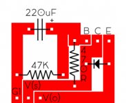
I've decided to try my hand at a capacitance multiplier for the front end of the Badger. I have never tried translating a schematic to a board, and a have only a tenuous grasp of the schematic. So before I blow-up my Badger...
I have attached a schematic of the multiplier OS proposed, and my perf-board layouts (based on the schematic) for positive and negative supplies. Can someone who knows better than I (which is 99.9999% of the people here) confirm whether I completed the board layouts properly?
I plan on connecting the multipliers with wire: Vs to the source, Vo to the output, and the grounds to the star ground on the Badger PCB (I'll probably attach them to the open spot right next to the speaker ground).
All sound good? Am I missing something?
Thanks!
Attachments
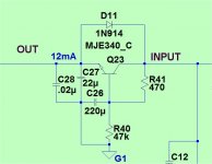
Remove C28 and locate the supply rail decoupling at the main current consumers in the load PCB.
C27 is missing.
The 470r & 47k give a 0.99:1 ratio for the base voltage to the input voltage.
You may want to look at decreasing this ratio a bit to ensure the base is protected from excessive ripple.
Your RC time constant for the 220uF & 47k is over 10seconds, so I think you could reduce it to 22k, or maybe even as low as 10k.
Remove C28 and locate the supply rail decoupling at the main current consumers in the load PCB.
C27 is missing.
The 470r & 47k give a 0.99:1 ratio for the base voltage to the input voltage.
You may want to look at decreasing this ratio a bit to ensure the base is protected from excessive ripple.
Your RC time constant for the 220uF & 47k is over 10seconds, so I think you could reduce it to 22k, or maybe even as low as 10k.
Andrew, thanks for your response!
Would 1K and 22K on the resistors be better?
Regarding the caps:
It is my understanding (see here) that capacitors that serve the purpose of C27 and C28 (decoupling) are already built into the HB layout (C10 & C11), which is why I didn't include them on my board.
Does that work?
Besides the items you pointed out, everything else looks fine?
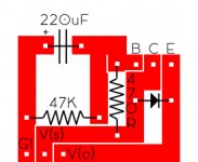
Something like this for builders to implement on a PCB. 4 can be fitted on a 50mmx50mm PCBway PCBs? For negative rail, how the schema changes?
Attachments
sanity check...
I have never had an issue with the HB. A friend upon listening suggested I try a PIO input cap though to see if that made a sonic difference. Took out the old MKP and provided for a new PIO...put everything back together being very careful about all the micas, shoulder washers and bolts, hook up etc...
Now with a dim bulb tester I never get the bulb to dim.
NO signs of burn on the bottoms of the output devices or on the heat sink. No burrs found.
I'm afraid to leave it going to check where the current is flowing through.
Funny thing is when all things are connected, all the current seems to be passing through the amp and not even charging the capacitors in the PSU or the boards.
When I checked the power supply separately: it's fine, passes dim bulb tester (the caps charge) : +/-63VDC.
I'd guess I am hooking it all up wrong but that seems silly; I have done the whole thing properly before. The boards connect to the PSU only at V+, V- and GND. Everything is labeled...
Is my best bet a complete "do over" starting with fresh boards assuming I somehow fried one or more outputs? I don't see how. I really don't understand what is going on. Help?
LC cap or no LC cap?
Hoping not too look foolish...
I have changed the input cap to PIO: not much sonic change.
I was hoping for a bit more "warmth".
From what I have read there are mixed reviews on using the LC cap. I'd try it but Im not sure under what conditions it is advisable.
I have used a 15V zener for my cascode having omitted R18 and having jumpered C to Z...does this preclude the use of any LC cap?
Hi all
I'm in the early stages of planning to build a pair of these little beasties. I'm hoping to drive a 6 ohm pair of Jamo floor standers with it, and thus need to make a couple of mods to the recommended output devices, in order to get around 200W into the speakers, using ±60V rails (sqrt(2*200*6) + losses.
The only thing is, I'm not clear on the exact calculations I ought to use to determine the correct devies. It would seem intuitive to simply increase the power handling capacity proportionally, so to use 200W devices instead of 150W, such as NJW3281/1302 or MJL3281/1302 pairs. However, we ought to be a bit more scientific than this, surely!
So, I found a few posts discussing the matter, including AndrewT's post 1395:
I'm afraid I haven't been able to work out the correlation between the figures. I understand that using multiple pairs of devices shares the load over them all, thus keeping them well within the SOA. But why 5 times? I understand it's a rule of thumb, but I would like to understand the reasoning here.
Rod Elliot's guide on SOA gives a different approach, with greater explanation, though also not without a confusing step:
Is the difference in the current figures in the first two equations simply a fuzzy safety margin? Even so, I'm having some difficulty making the figures align.
If I apply these equations to my case, assuming the resistive part of my load will be around 4 ohms minimum:
 ... Now, dividing by the derated power handling capability of my suggested device @ 75° (128.5W), we get 3.5, meaning 4 pairs, which obviously won't work on this design. If I do the calculations again, using a 230W device such as MJL4281, I get 3.2, amounting to 4 pairs again.
Are perhaps my safety margins too generous? Even lowering the expected case temperature by ten degrees suggests it's probably too much. Seems however I look at it I'll need some pretty big heatsinks! Perhaps the rails voltages are still too high? I thought that with my expected load, they should work out to be the same as the standard 8 ohm badger.
All this and I haven't even considered any changes I might need to make to the driver devices!
I hope somebody more knowledgable than I might be able to assist.
Kind regards, Andrew
http://www.diyaudio.com/forums/soli...oney-badger-build-thread-140.html#post4243673
I'm in the early stages of planning to build a pair of these little beasties. I'm hoping to drive a 6 ohm pair of Jamo floor standers with it, and thus need to make a couple of mods to the recommended output devices, in order to get around 200W into the speakers, using ±60V rails (sqrt(2*200*6) + losses.
The only thing is, I'm not clear on the exact calculations I ought to use to determine the correct devies. It would seem intuitive to simply increase the power handling capacity proportionally, so to use 200W devices instead of 150W, such as NJW3281/1302 or MJL3281/1302 pairs. However, we ought to be a bit more scientific than this, surely!
So, I found a few posts discussing the matter, including AndrewT's post 1395:
My usual rule for a BJT output stage is approximately 5 to 6 times the maximum power output for the total Pmax of all the devices.
Using 5times I would end up with 1200W of total Pmax
3pr of 200W devices meets that guideline.
I'm afraid I haven't been able to work out the correlation between the figures. I understand that using multiple pairs of devices shares the load over them all, thus keeping them well within the SOA. But why 5 times? I understand it's a rule of thumb, but I would like to understand the reasoning here.
Rod Elliot's guide on SOA gives a different approach, with greater explanation, though also not without a confusing step:
Having discounted the idea of any 'rules-of-thumb', I'm going to give you one anyway. Let's assume that you want to deliver 100W into 8 ohms, so you need a power supply with ±42V rails (I'm going to ignore losses here). The amp must also be able to drive nominal 4 ohm loads, so expect the minimum impedance to be 3 ohms. Worst case (resistive load) dissipation is therefore ...
I = V / 2 / R = 21 / 3 = 7 AmpsThis accounts for the resistive part of the load, and as we saw above, the reactive part of the load causes dissipation to double. Just like second breakdown, we aren't interested in the average dissipation - this influences the size of heatsink needed, but not the transistor's safe area. Therefore, Ppeak will be ...
P = V / 2 * I = 21 * 8 = 168 Watts (peak)
Ppeak = P * 2 = 168 * 2 = 336 WattsRemember that this is the real peak power that the devices must be able to handle, and they must be able to do so at elevated temperatures. We want to be safe, so we have to choose a temperature that is realistic, given the type of service for which the amp is designed (home theatre, live sound, disco, etc.). For the sake of the exercise, we'll assume a fairly safe usage such as domestic hi-fi, and assume that the transistor die may get to 75°C (we'll use a really good heatsink). The transistor peak power dissipation must never exceed the maximum allowable, so we have to ensure that peak power remains below 140W (using MJL4381/4302 devices).
Based on these quick assumptions, we will need 2.4 transistor pairs to handle the power. Obviously we can't get 0.4 of a transistor, so we will need 3 pairs of output devices to handle the load.
Is the difference in the current figures in the first two equations simply a fuzzy safety margin? Even so, I'm having some difficulty making the figures align.
If I apply these equations to my case, assuming the resistive part of my load will be around 4 ohms minimum:
I = V / 2 / R = 30 / 4 = 7.5A
P = V / 2 * I = 30 * 7.5 = 225 W (peak)
Accounting for the reactive aspect of the load, this gives 450W
P = V / 2 * I = 30 * 7.5 = 225 W (peak)
Are perhaps my safety margins too generous? Even lowering the expected case temperature by ten degrees suggests it's probably too much. Seems however I look at it I'll need some pretty big heatsinks! Perhaps the rails voltages are still too high? I thought that with my expected load, they should work out to be the same as the standard 8 ohm badger.
All this and I haven't even considered any changes I might need to make to the driver devices!
I hope somebody more knowledgable than I might be able to assist.
Kind regards, Andrew
http://www.diyaudio.com/forums/soli...oney-badger-build-thread-140.html#post4243673
- Home
- Amplifiers
- Solid State
- diyAB Amp The "Honey Badger" build thread