Os recommeds to use a tested pair of power bjt ,howto get those. ? From a working amp desolder or what ? Buy more pcb's ? Another question here is no seperate earth. Ygveos said in the spooky ips noise disapired by by shorting the diode + 10R solved the problem how about badger?
Andrew how do you measure power bjt lets say 20 30 40 50 60 70 V , what tolerance do you use as reference ?
Would a mat12 or similar be better for inputstage or the smd series of matched a little cheaper ?
Lähetetty minun H60-L04 laitteesta Tapatalkilla
Andrew how do you measure power bjt lets say 20 30 40 50 60 70 V , what tolerance do you use as reference ?
Would a mat12 or similar be better for inputstage or the smd series of matched a little cheaper ?
Lähetetty minun H60-L04 laitteesta Tapatalkilla
I just read ostippers last post , i bought ksa992 ksc1845fta this time they are closer hfe with dmm tester first buy 350 to 480 now silimar in the 420 to 470 I bought 150pcs and bc550 bc 560 and the ksa1015yta 1815yta but these are around 155 & 190+ . Whats your opinion on matching npn to pnp Vce and hfe
Lähetetty minun H60-L04 laitteesta Tapatalkilla
Lähetetty minun H60-L04 laitteesta Tapatalkilla
I had HF noise only once. It was generated by VHF oscillation in my first lateral mosfet amplifier. Oscillation was killked by adding a small cap between N channel sources but Mosfet solution does not apply here.
Nevertheless maybe mild oscillation is causing it? Is zoebel cold? Resistor across the output coil?
cheers,
PS I always use non inductive cap and resistor in zoebel. Just in case.
PS 2 I just remembered, I had noise in Badger in one configuration. It came from poor quality long commercial interconnectors between active crossover and ammp's input but that noise was mid frequency as well but not hum. Quality connectors I made by myself cured it completely.
Last edited:
I will buy a new pcb , its taken it's toll pluggin the fastons and re and resolder.Good board thou , user error on working two boards at once it had been years doing other power amps so rusted skills. Desoldering was time consuming lesson learded with gold plated boards for years to come. Measure value , write down, solder enter value in ltspice . I must say that the mje15034/35 shows hfe on dmm both around 250 to 273 with four pcs the mje15032 100 and 15033 200- 203 on the dmm 5 pcs .Well parts are from mouser . Checl the semis too I got mje 340stu in mje350stu package. Buying the boards want to finish in stereo otherwise here from you on the slew side.
Lähetetty minun H60-L04 laitteesta Tapatalkilla
Lähetetty minun H60-L04 laitteesta Tapatalkilla
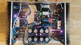
I have finally had time to test a bit more. I have removed the safety earth from the chassis temporarily. The input signal wires going from the RCA connectors at the chassis to the amp pcbs were also removed.
Any ideas on where to look next? Here is a picture as well (I will twist the power supply wires instead of braiding them, as suggested by jwilhelm and AndrewT)
Thanks
If I leave the star ground floating from the chassis there is a relatively loud noise. This noise sounds like white noise over the entire frequency range. So the noise from the bass, midrange and tweeter is roughly equally loud.
- If the star ground is connected to the chassis most of the noise disappears, leaving just a faint HF (white noise like) sound in the tweeter. It is hard to see this wire on the picture, but it's the black one going from the PSU ground to the lower left corner of the transformer cover.
- In both wiring cases mentioned above there is a clicking sound in the speakers every time you touch the chassis with your hands.
Any ideas on where to look next? Here is a picture as well (I will twist the power supply wires instead of braiding them, as suggested by jwilhelm and AndrewT)
Thanks
Attachments
Hi OS,
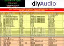
I'll post some pics tomorrow, I used the official BOM and got everything from Mouser and Digikey. I'll dig up my BOM and post that too. I'll triple check all settings and report back.
PJN
Hi OS/Guys,
I double checked my build, all parts were from Digikey and I used the DIYAudio BOM. Below I've attached a few pics of my build and the BOM. I checked calibration tonite CSS read 8.25vdc across R14, Bias TP1 - TP2 was 44 mV, offet was about 1 mV for each channel. I adjusted to these from the DIY build guide. Zener referenced cascade with TMC for the VAS. The hiss is present with or without source connected, it was even there when I disconnected the inputs to the board. You need to be close to the tweeter to hear it, within 2-3 ft. Maybe some of the devices that I got from Digikey were defective. If you have any ideas let me know, I can replace them.
Appreciate any help.
PJN
Attachments
Hi OS/Guys,
I double checked my build, all parts were from Digikey and I used the DIYAudio BOM. Below I've attached a few pics of my build and the BOM. I checked calibration tonite CSS read 8.25vdc across R14, Bias TP1 - TP2 was 44 mV, offet was about 1 mV for each channel. I adjusted to these from the DIY build guide. Zener referenced cascade with TMC for the VAS. The hiss is present with or without source connected, it was even there when I disconnected the inputs to the board. You need to be close to the tweeter to hear it, within 2-3 ft. Maybe some of the devices that I got from Digikey were defective. If you have any ideas let me know, I can replace them.
Appreciate any help.
PJN
Typically , with my good ears ... and 91db/w tweeters - I need to put my ear
right on the tweeter to hear the hiss. The room needs to be silent , as well.
This was with my wolverine ( nearly the same as the badger) with higher
global gain 36X.
OS
Have you tried it without the speaker protection? It sounds like something is chassis grounding your audio signal ground.
I have tried with the ground wire from the speaker protection board detached from the star ground, so that the power supply to the protection board is floating, and it made no difference. With the input shorted, I still have the HF noise in the tweeter. My build is according to the BOM with parts from Mouser
Try a typical small 4.7uf /50V wima input cap instead of those "boutique" ones.
OS
Hi Os,
I can do that, in fact I may already have some in my spare parts bin.
PJN
I've recently started a Honeybadger build and have to say the guides have been really helpful. I got all the parts as per the BOM from Farnell using the best caps I could fit in the board along with metal film 1% resistsors (some bits from Hifi-Collective) in nearly all positions.
I've read quite a few books on amp design but never attempted to build a full power amp before, I'm glad to say that the badger with ready made PCB's really helped me get to the on-ramp (I've built quite a few speakers, some with complex crossovers and some moderately complex Arduino / AVR stuff).
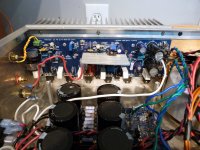
However, I don't understand what R53 and R54 are for and in fact I'm worried that they will fry if a fuse goes, as they seem to be very low resistance in parallel with the main input. Does anything protect them from failure in the case of a blown fuse? Any help understanding these resistors better would be great.
I've read quite a few books on amp design but never attempted to build a full power amp before, I'm glad to say that the badger with ready made PCB's really helped me get to the on-ramp (I've built quite a few speakers, some with complex crossovers and some moderately complex Arduino / AVR stuff).
However, I don't understand what R53 and R54 are for and in fact I'm worried that they will fry if a fuse goes, as they seem to be very low resistance in parallel with the main input. Does anything protect them from failure in the case of a blown fuse? Any help understanding these resistors better would be great.
R53 & R54 are bypasses across the supply rail fuses.
These can be useful for setting up the amplifier and checking what current flows to different parts of the circuit, particularly if you initially build without drivers and/or without output devices, or only one pair of output devices until testing is completed.
But, I don't like them. Instead I drill out blown fuses and insert the required resistor inside the fuse cartridge and resolder the ends.
This way I can insert the resistor, 1r0 or 10r are useful values, during testing and then insert real fuses later.
BTW.
check for output offset with one fuse removed, then swap out the other fuse.
As an aside if I have a current limiting and variable voltage bench PSU capable of 32-0-32, could I just use the current limiter to cut if the amplifier exceeds 50-100mA and slowly bring up the voltage instead of the 10R resistors in the fuse holders?
I know I won't get anywhere near full power, but my guess is it would let me test the amp is generally working before proceeding to a full PSU.
Does this approach seem reasonable, or should I still go with the 10R across the fuse?
I know I won't get anywhere near full power, but my guess is it would let me test the amp is generally working before proceeding to a full PSU.
Does this approach seem reasonable, or should I still go with the 10R across the fuse?
R53 & R54 are bypasses across the supply rail fuses.
These can be useful for setting up the amplifier and checking what current flows to different parts of the circuit, particularly if you initially build without drivers and/or without output devices, or only one pair of output devices until testing is completed.
But, I don't like them. Instead I drill out blown fuses and insert the required resistor inside the fuse cartridge and resolder the ends.
This way I can insert the resistor, 1r0 or 10r are useful values, during testing and then insert real fuses later.
BTW.
check for output offset with one fuse removed, then swap out the other fuse.
Thanks Andrew,
I understand what they are for now, I will remove them once I've finished initial testing of the amp. I have not installed drivers or power devices yet, so I will go ahead and test the IPS and VAS in isolation with fuses removed (as I've already soldered R53/4 in).
- Home
- Amplifiers
- Solid State
- diyAB Amp The "Honey Badger" build thread