I have it in between but because of size a little closer to the pcb. Short legs on that one
It looks like your heat sink is all one piece? I have two heat sinks for each side of the chassis, that butt together. "Q13" would be smack dab in the middle.
Another question... Since I will be using TO-126, TO-220-3, and TO-264 on my heat sinks; Are the plastic(vinyl) insulation washers/bushings standard for all devices? The mounting holes vary from:
TO-220-3: 1.3mm Deep/ radius 3.6 to 4mm
TO-126: 3.5mm Deep/ radius 3.2mm
TO-264: 5mm Deep/ radius 3.5mm
Perhaps I'm not using the correct terminology in my search? is there a more accurate name on these?
TO-220-3: 1.3mm Deep/ radius 3.6 to 4mm
TO-126: 3.5mm Deep/ radius 3.2mm
TO-264: 5mm Deep/ radius 3.5mm
Perhaps I'm not using the correct terminology in my search? is there a more accurate name on these?
I call them "top hat" washers.
But that is not right, only descriptive.
The To220 and To3p washers are different. OD is different, depth of sleeve is different.
With care and a very sharp knife you can cut down the depth of the sleeve.
Use a metal washer on the top of the top hat. That stops the bolt/screw head digging into the soft-ish plastic (probably nylon).
They can split when stressed.
TO-3P and TO-220
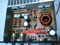
As you can see from the car amp below , most OEM's don't trust the
thermal conduction provided by standard package mounting.
They use a metal bar over the row of devices , applying the torque
over the die , not on the package hole.
This might not matter as much with the TO-220 drivers (or to-126 Vbe)
on the Badger , but would better the thermal derating (conduction)
on any of the power devices. The car amp pictured also does this
for the TO-220's because they are the switch- mode devices and
the amp runs in a hot car trunk !
OS
Attachments
Thanks for the tips!I call them "top hat" washers...With care and a very sharp knife you can cut down the depth of the sleeve. Use a metal washer on the top of the top hat. That stops the bolt/screw head digging into the soft-ish plastic (probably nylon).
They can split when stressed.
Shoulder Washer is the correct North American term for those washers.
 Thanks!
...use a metal bar over the row of devices , applying the torque over the die , not on the package hole...
...would better the thermal derating (conduction)
on any of the power devices. !
OS
I've seen this technique on an inverter I recently took apart to scavenge parts from... Your e-waste discussion in another thread inspired me to attempt a green/ recycled version of the badgers once I progress as an amp builder/ enthusiast.
I'd like to design my own e-waste amp someday, although that is another discussion altogether
")
Thanks for the tips!
I've seen this technique on an inverter I recently took apart to scavenge parts from... Your e-waste discussion in another thread inspired me to attempt a green/ recycled version of the badgers once I progress as an amp builder/ enthusiast.
I'd like to design my own e-waste amp someday, although that is another discussion altogether
But , it is a superior technique than can be applied to a new build ,as well.
PS - the fact that the technique was acquired from e-waste does not
denigrate it, In fact , the way most forum amps are built is primitive.
PS2 - just a opinion.
OS
But , it is a superior technique than can be applied to a new build ,as well.
PS - the fact that the technique was acquired from e-waste does not
denigrate it, In fact , the way most forum amps are built is primitive.
PS2 - just a opinion.
OS
I completely agree. I didn't mean that it was inferior in any way
I was just commenting, as I thought it was cool that with my minimal experience I actually recognized the technique (even if I didn't recognize the value at first) When clamping use a bolt/screwing fixing on each side of the transistor.
Reduce deflection of the clamp bar by keeping these two screws/bolts close to the transistor.
In the example pictured above three screws/bolts should be used for the two transistors.
The clamp as shown will create very high pressure at the edge of the transistor nearest the bolt. Eventually the far side of the transistor lifts off the pad and no heat transfer can occur when "lift off" has occurred. Reduced heat transfer where the pad pressure is less than recommend by the manufacturer.
When clamping use a bolt/screwing fixing on each side of the transistor.
Reduce deflection of the clamp bar by keeping these two screws/bolts close to the transistor.
In the example pictured above three screws/bolts should be used for the two transistors.
The clamp as shown will create very high pressure at the edge of the transistor nearest the bolt. Eventually the far side of the transistor lifts off the pad and no heat transfer can occur when "lift off" has occurred. Reduced heat transfer where the pad pressure is less than recommend by the manufacturer.
I agree so please explain how having a bar with one bolt for two transistors can ever be as good as having a single bolt into the center of each transistor where the designers put it. Those car amps are made that way for ease of assembly, not because it is superior.
I can't explain that.please explain how having a bar with one bolt for two transistors can ever be as good
I have said:
When clamping use a bolt/screwing fixing on each side of the transistor.
Yes know. I guess I was agreeing with you though it didn't come out that way. IMO, the devices were not designed to be clamped. They were designed to be bolted through the hole provided. Clamping several devices with one "bar" would require that all of the devices were exactly the same thickness. I'm not so sure that all the plastic cases can be trusted in that regard. In cases where there are a mixture of TO-3P and and TO-220 a continuous bar is useless. The bare also requires that more holes be tapped. I have yet to have any issue with attaching the devices with the provided holes.
I agree so please explain how having a bar with one bolt for two transistors can ever be as good as having a single bolt into the center of each transistor where the designers put it. Those car amps are made that way for ease of assembly, not because it is superior.
No , having the torque centered on the semi will distribute the force equally
over the whole device.
To-264/3p the bolt tightens down the end of the tab (slug) thermal compound
will "ooze" out around the screw first .... under the die end later.
MT-200 has 2 screws ... industrial triacs and the old TO-3 - 2 hole ,
this configuration acts like the bar in the car amps.
I did see one TO-3P industrial motor control , it had a 12mm aluminum bar with
3 -4mm bolts over 4 semi's.
In the real world , I would say you might get 5-10% better thermal derating
with the bar.
A test of this would be to get "plasti-gauge" at the auto store , compare
the two methods. I bet the plasti-gauge would be much wider under
the screw hole and even wider under a MT200 or the bar (wider = less 1/1000").
PS - multiple holes (screws) over the length of the bar is what I meant.
If the single screw bar was larger (>4mm bolt) , I also bet it would at least
match standard mounting .... plus only require one hole. This most
likely is the reason the cheap car amps use this method.
OS
hello OS
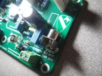
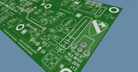
this is only an idea of adding a RCA input connector to the Honey Badger for quick test audio what you think ?
Regards
Juan
I actually would do this on something modular (like the slew's). Would save
time unscrewing the input terminal wires after swapping.
Badger is a finished product , build it once ... forget about it.
OS
- Home
- Amplifiers
- Solid State
- diyAB Amp The "Honey Badger" build thread