The other thing with the yuanjing amps I have is the great silly silicon thermal pads. I've chucked them, filed the heatsinks and put a little thermal compound on. The heatsinks get pleasingly warm now.
Thermal pads can work, but not 3mm thick under low pressure and simply to avoid the higher profile caps. A Russian link I found had this problem which made me check mine.")
???????? ® Blog Archive TAS5630 300Wx2 50V/4Ohm
Thermal pads can work, but not 3mm thick under low pressure and simply to avoid the higher profile caps. A Russian link I found had this problem which made me check mine.
???????? ® Blog Archive TAS5630 300Wx2 50V/4Ohm
Last edited:
Ya, because cheap solution.
At "normal" levels this wont be a problem, but if you going for higher continuous output, it doesn't.
You may try copper pads as thermal coupler for the "extra bit" of heat transfer, like so:
TPA3251 (TPA3255) aka ?Model Tiny? in Aluminiumgehäuse ? #360customs
At "normal" levels this wont be a problem, but if you going for higher continuous output, it doesn't.
You may try copper pads as thermal coupler for the "extra bit" of heat transfer, like so:
TPA3251 (TPA3255) aka ?Model Tiny? in Aluminiumgehäuse ? #360customs


A second board has been added to my system to drive a 12" subwoofer in a 60L ported box. The switch off noise is a problem with this arrangement. I had the sub in 28L sealed box before and the cone movement was noticeable but not dangerous.
This second board has a small sub board with the low pass filter on it, but the main board is virtually the same and I guess it's the 12V supply rail dropping that is the problem.
Does anybody have a simple mute circuit that kicks in early on main voltage loss I an copy? I could design something, but if there is a tried and tested arrangement, that would be best.
Top job, thank you
I found a 3 pin TO-92 equivalent to the 3809 (no reset input and O/C output) which should allow me stick it down on the PCB with a couple of resistors,cap and the zener where the missing "Shutdown" connector is. I'll probably solder the bits to a small piece of stripboard first.
Trying to spider wire a 5 pin SM without the right kit and general purpose PCB is not beyond me, but....
The last auto reset I designed was for a Z8000. I seem to remember a 4000 series CMOS comparator running off the nicad static 6264 RAM storage rail monitoring the 5V processor rail. There was another connection into the 12V rail, but I can't remember what that was for now.
A 3 pin chip with hysteresis, guaranteed time delay and a 1.1V minimum operating voltage is a whole lot easier!
MCP121 450E/TO
Last edited:
The car.
Saab 7 channel amp with a Kenwood D amp and own built JBL sub box is sounding good. I feel some mods coming on to shoehorn some of these little chips in there.
The stock amp is rated 70W per channel (2R) so is fairly capable and has some step-up inside. Definitely less distortion than the quoted 50W per channel mosfet head units.... Only 12V!
I think 48V is the way to go. Any ideas for a (400W ?) step up from 12V DC?
24V if this sounds expensive
I'm not sure which is good, but there are several offers on aliexpress.
Maybe somebody has any experience with one of those or anything similar...
https://www.aliexpress.com/item/Hig...id=39f31b06-9849-4048-8f72-1ae18cdbccc4&tpp=1
https://www.aliexpress.com/item/800...id=39f31b06-9849-4048-8f72-1ae18cdbccc4&tpp=1
https://www.aliexpress.com/item/201...02.2.W3wcmv_2114.13010208.99999999.397.6hZyXj
Last edited:
Take the 10A input current limit into account. Better go for 20A device.
http://www.aliexpress.com/item/32729978967/32729978967.html
http://www.aliexpress.com/item/32688927073/32688927073.html
http://www.aliexpress.com/item/32729978967/32729978967.html
http://www.aliexpress.com/item/32688927073/32688927073.html
Last edited:
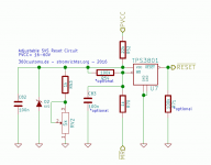
Low voltage cutoff works well. Thankyou DrMord.
20K and 2K2 voltage divider with MCP 121 which has a "4.5V" actually 4.38V typical switch point. This is about 43V for a 48V PSU. 6.2V protection diode and 100nF cap fitted.
All the rushing and crackling noises on power down have gone
This is on the Yuanjing 2channel board (copy of TI development) I have on the mid/treble channels. The subwoofer PCB is almost identical, but where R39 & R11 go-to means taking the heatsink off again. R11 may not exist on this version, but the pullup will be there. More surgery
Lordy know how loud these amps will be in the car when I get to it. Fane 97Db mids and Faital Pro compression drivers (108dB) with a self designed Econowave type crossover and 14" wave guide go very loud cleanly.
I've got JBL speakers in the car. Much less efficient, but. 48V and 2~3R drivers ought to be pretty lively. The sub has 2* GT5-10 JBL drivers on a Kenwood D amp and that kicks. Once I get the other 7 speakers on the TAS amps....... There are 11 drivers plus the 2 subs in there currently.
I'll use some double sided sticky pads and a couple blobs of epoxy to stick these down.
The subwoofer amp does not follow the development board like the mid range (red PCB) and some tracks are deleted. The 100R series, 47K pullup and cap are all there under the heatsink though. The orange wires go to the RESET circuits, red to +48V and brown to 0V.
Works very well and there are no clicks, pops, rushing or other annoying noises!
An externally hosted image should be here but it was not working when we last tested it.
The subwoofer amp does not follow the development board like the mid range (red PCB) and some tracks are deleted. The 100R series, 47K pullup and cap are all there under the heatsink though. The orange wires go to the RESET circuits, red to +48V and brown to 0V.
Works very well and there are no clicks, pops, rushing or other annoying noises!
Last edited:
- Status
- This old topic is closed. If you want to reopen this topic, contact a moderator using the "Report Post" button.
- Home
- Amplifiers
- Class D
- DIY Yuanjing TAS5630b module fix