Sorry Marce,did not get it . Do I need to make the upper copper layer into 4 blocks like I did with ground (bottom layer) to make it isolated? or just routing it through inductors as you suggested should do the isolation?
I am using the bottom layer only for ground (s)and using top layer for VBUS1 and VBUS 2 only .VBUS 1 and 2 are physically separated into two layers at the adum4160 level. But the pi filters are just laid out as tracks on top layer and not separated out into blocks as in ground plane. IS that acceptable?
I am using the bottom layer only for ground (s)and using top layer for VBUS1 and VBUS 2 only .VBUS 1 and 2 are physically separated into two layers at the adum4160 level. But the pi filters are just laid out as tracks on top layer and not separated out into blocks as in ground plane. IS that acceptable?
And you said you weren't having much luck with Eagle. It looks good! Remember to change the DRC rules to suite the PCB manufacturer.here is the updated board
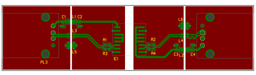
I would do it somewhat like this (pain") ) I have laid out the circuit in the schematic I posted earlier as its easier to show a pretty picture than try and explain un words.
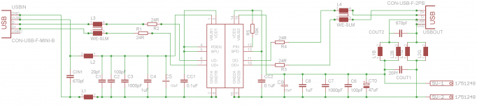
) I have laid out the circuit in the schematic I posted earlier as its easier to show a pretty picture than try and explain un words.
Notice the power is routed as tracks not as a copper pour to minimise capacitive coupling.
Also not how the PI filters are laid out (critical) and how the ground planes split (very critical).
Hope this makes it clearer...
Marc
Edit: I've used PTH USB connectors (they were in my library) for a DIY project you may find these less susceptible to breakage when plugging cables in and out, just a thought.
Quick link:
WE-CBF HF SMD EMI Suppression Ferrite Bead (High Frequency) - Product Catalog Passive Components
) I have laid out the circuit in the schematic I posted earlier as its easier to show a pretty picture than try and explain un words.Notice the power is routed as tracks not as a copper pour to minimise capacitive coupling.
Also not how the PI filters are laid out (critical) and how the ground planes split (very critical).
Hope this makes it clearer...
Marc
Edit: I've used PTH USB connectors (they were in my library) for a DIY project you may find these less susceptible to breakage when plugging cables in and out, just a thought.
Quick link:
WE-CBF HF SMD EMI Suppression Ferrite Bead (High Frequency) - Product Catalog Passive Components
Attachments
Last edited:
Other than an academic exercise, what's the point of this project? The ADuM chip is limited to slow or full speed data rates. That means means no sample rates above 96K and adaptive mode transfers, only, because the async transfer mode requires high speed data rates.
Also, instead of those wiggly traces, just mount the connector on the other side of the PCB.
Also, instead of those wiggly traces, just mount the connector on the other side of the PCB.
Other than an academic exercise, what's the point of this project? The ADuM chip is limited to slow or full speed data rates. That means means no sample rates above 96K and adaptive mode transfers, only, because the async transfer mode requires high speed data rates.
Also, instead of those wiggly traces, just mount the connector on the other side of the PCB.
Squiggly lines!!!! Don't forget this is just a quick example layout, mainly to get across the importance of separation between areas when filtering for EMC is used, so its a useful tip for people to incorporate in their layouts if they want
I know this works as the technique has been tested to 18GHz immunity for a certain project that I worked on where we fine tuned all aspects of the design to achieve what we had to.
Having both connectors on the same side of the board is better for assembly, having a housing done etc. also soldering, having it on the other side would make the lines a little prettier though, and would be quite acceptable for hand assembly. The squiggle is because the D-/D+ lengths were a little out of spec for skew...normally this would be on a multilayer board so the diff pair traces would be a more sensible size and the wiggle wouldn't be as noticeable.
I have left any top layer ground pours of my little example design for clarity, they can be added, then I would have to add some stitching vias.
Other than an academic exercise, what's the point of this project? The ADuM chip is limited to slow or full speed data rates. That means means no sample rates above 96K and adaptive mode transfers, only, because the async transfer mode requires high speed data rates.
.
Tam o you have anything better to suggest for isolating two sides of USB?
Tam o you have anything better to suggest for isolating two sides of USB?
There aren't common ICs available to isolate USB at higher speed.
The trend these days, if you design from scratch, is thus to isolate the I2S lines rather than the USB lines.
There aren't common ICs available to isolate USB at higher speed.
The trend these days, if you design from scratch, is thus to isolate the I2S lines rather than the USB lines.
Yes and USB 2 full speed can support up to 24bit 96Khz which works for usual audio. I do not think speed has anything to do with mode of transfer, but I might be wrong.
Yes and USB 2 full speed can support up to 24bit 96Khz which works for usual audio. I do not think speed has anything to do with mode of transfer, but I might be wrong.
Wrt the mode of transfer, iirc (I'd have to dig the references for this), the adum4160 doesn't pass some handshake signals back to the host, which prevent proper operation of the asynchronous mode.
Yes and USB 2 full speed can support up to 24bit 96Khz which works for usual audio. I do not think speed has anything to do with mode of transfer, but I might be wrong.
Speed has everything to do with transfer mode. Async transfer mode is a feature of USB Audio Class 2 and USB Audio Class 2 requires USB 2.0. What distinguishes USB 2.0 from USB 1.1 is a 480Mbps base data rate. The ADuM isolator cannot operate at 480Mbps and therefore does not support USB 2.0 or any features for which USB 2.0 is a prerequisite.
If you use advertizing BS as a source for technical specs, good luck with your project.
Max I managed some how, it was a steep learning curve.Still trying to figure out how to make the 4 edges parallel. Any shortcuts?
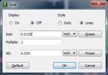
Yeah it's all these little annoying things that take a while to work out. I recommend you go to 'View > Grid' in Eagle and set it the 'size' and 'alt' lower. I've included a screenshot of my settings (but I usually turn grid lines on too). You might need to go lower though. Once you've set these, don't change them as if you place something in the PCB, then change them, then place something else they may not line up.
Attachments
And you said you weren't having much luck with Eagle. It looks good! Remember to change the DRC rules to suite the PCB manufacturer.
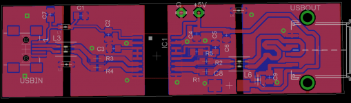
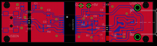
Max necessity is the mother of everything ,I somehow managed it over past few days. And here is the final board with ground planes on top and bottom with traces carrying power and data as Marc suggested. Just need the idea on capacitors .Marc also suggested ferrites debating between 670pF and 1nF. Also wondering what to do with the caps in original design. (47uf and 10uf.). Unfortunately I lost the link between brd file and sch file n eagle and there wont be any annotations .So modifications might not be easy
.Attachments
Speed has everything to do with transfer mode. Async transfer mode is a feature of USB Audio Class 2 and USB Audio Class 2 requires USB 2.0..
The SaviAudio SA9027 USB Reciever claims Asnyc transfer mode with USB full speed interface.
I would love to take the credit, but the EMC stuff is from work I have done with an RF engineer (also an EMC guru) on a project I have worked on for a couple of years, the layout was my contribution. But we know it works and works well for keeping noise from getting through.
- Status
- This old topic is closed. If you want to reopen this topic, contact a moderator using the "Report Post" button.
- Home
- Source & Line
- Digital Line Level
- DIY USB isolator