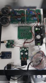
Hello, I'm still continuing to build a DAC, I use supercapacitors and +5-5V power lines LT3045 smoothed 2x supercapacitors 10F in series, the green ones, I would also try the batteries but I don't know how to connect and charge them, for now I'm playing SPDIF, USB is ready, the output is bisesik transformer.
Attachments

That’s great to hear. I built the ACA mini and am running it in on a 6s lipo and it’s just amazing sounding.I also enjoy the D3 for a long time now. Thank you once again to Ryan for all the work he put into this DAC. To be honest, most of the mods i made to this DAC were removed again, because the difference was not big enough for me. What stayed is my battery PSU with LifePo4 Batteries. This was really a game changer for this DAC. It sound even better now. Of course 22 LifePo4s are a bit overkill, but i wanted to have all the voltages battery based and I receive the batteries very, very cheap... The only thing I didnt try was the supercapacitors, perhaps I will try it in the next months.
https://www.diyaudio.com/community/threads/pictures-of-your-diy-pass-amplifier.166784/page-327
Your setup looks very good! I do not think the hassle with batteries on 5v will give you a worth while improvement, especially because you will need a regulator behind the batteries to produce the 5v and you already have the ultracaps on the boards.Hello, I'm still continuing to build a DAC, I use supercapacitors and +5-5V power lines LT3045 smoothed 2x supercapacitors 10F in series, the green ones, I would also try the batteries but I don't know how to connect and charge them, for now I'm playing SPDIF, USB is ready, the output is bisesik transformer.
Nice to see you are using the ultracaps, did you compare with the oscon? I would like to know if it is worth while.
is your IV resistor on the secondary side of the transformer?
Hi, I'm using ultracap as recommended by wlowes, sometimes they charge for about 1 minute when turned on. The sound seems better to me, I can't judge 100%. I use resistors on the primary and secondary for the transformer. I'll try buffers and another transformer as recommended by bisesik.
Looking for this regulator as long lead times, any ideas please? Google not showing availability…..
https://www.mouser.co.uk/ProductDetail/595-LM317MQDCYR
https://www.mouser.co.uk/ProductDetail/595-LM317MQDCYR
I had the same issue, I ordered an alternative that is a tad bigger but if you are handy it will fit on the pcb: https://nl.mouser.com/ProductDetail/863-NCV317MBDTRKG
in below picture it is at V1 position.

in below picture it is at V1 position.
Hi everyone
I’m coming back to this D3 project after getting mine operational towards the end of 2020.
Essentially, I spent a year learning enough and working with Ryan and others to be able to assemble my first DAC Based on his D3 boards.
I’m still using IanCanada’s original S/PDIF Interface board and Asynchronous FIFO with upgraded Crystek clock board I picked up second hand.
I’m feeding the signal on to Ryan’s V2 I2S to Simultaneous board and then to a pair of D3 boards.
I have separate D3 CMx based power supplies for the D3 boards and a couple of Salas SSLV1.1 boards fed by another transformer providing other necessary 5V and 6V supplies needed for the boards.
In 2020 I think I was just happy it worked and sounded good.
The output level was a bit low as I took the easiest way out with the i/v conversion by just using some MK132 resistors I had on hand.
I had acquired a few other options to use for gain on the output of the DAC and had considered other i/v resistors but I had burnt out on the project a bit.
Now I would like to sort things out further by re-examining the i/v conversion and adding some gain at the output.
I acquired an old SEN i/v stage kit board with heatsinks in the swap meet a while ago. I’m not sure this is what I want to use because it requires another power supply…or two? They are supposed to be floating. Two 8.4V NiCad batteries were recommended in the original instructions. I am not even sure it’s possible to properly use a single board since I am running two D3 boards.
My other option is a pair of bisesik’s DAC output transformers I purchased used from another member who also built Ryan’s D3 project.
This is kind of where I left off back in 2020.
I was trying to figure out how to properly connect these transformers and also what needed to be done regarding changes to i/v resistors, their location (before the primaries or after the secondaries) and any other modifications to the D3 circuit necessary in order for things to work right and for me to avoid sending anything up in smoke.
It raised questions about how I am using my pair of D3 boards.
When I first inquired Bisesik was nice enough to provide some illustrations when I asked about proper connection of the transformers in his thread.
There was some confusion as I described my D3 build as being “Dual/Mono” ( I assumed this was an accurate term for using two 1541 chips and dedicating one to each channel…left or right.)
He posted a wiring illustration, and then revised his response and posted another illustration based on the fact that he realized the transformers I had acquired had two primary coils and that what I wanted to achieve was wiring two D3 boards for “differential“ connection.
I was left sitting and scratching my head about a variety of terms I have encountered while trying to understand the use of more than one TDA1541 to process signals in a DAC.
Simultaneous, parallel, dual/mono, balanced, differential…all terms I came across and they all kind of left me in a fog. I am more of a glorified LEGO builder with these electronics projects and don’t understand a whole lot about circuit design or chip implementation.
What I can say is that I have re-examined the connections between my V2 I2S to Simultaneous board and my D3 boards.
I am not using any of the inverted signal connections for the “DR” or “DL“ signals running to my D3 boards.
I have the “DL1” and “DL2“ signals connected to “DL” and “DR” respectively on my lower D3 board.
I have the “DR1” and “DR2” signals connected to “DR” and “DL” respectively on my upper D3 board.
I have spent time researching in the Building the ultimate NOS DAC with TDA1541 thread.
There were some posts by ecdesigns with terminology and different methods of processing the signal with the TDA 1541.
ecdesigns said:
“If you already have LE, BCK, DL and DR,
(1) SE mode: feed these 4 signals to one chip.
(2) Parallel mode: feed LE, BCK, DL, DL to left channel chip, feed LE, BCK, DR, DR to right channel chip.
(3) Balanced mode (simplified, not fully correct): feed LE, BCK, DL, -DL (inverted DL) to left channel chip, feed LE, BCK, DR, -DR (inverted DR) to right channel chip.”
So it would seem I have things wired for “parallel mode”.
There was no specific mention of “differential mode”.
I did come across another thread where the OP related they were interested in using two tda1541 chips for ‘differential” output.
They opened the thread with an illustration and description of the “differential” scenario…and the resulting benefits of its use.
The thread:
https://www.diyaudio.com/community/threads/the-best-tda1541a-differential-out-nos-dac.275474/
In this scenario they appear to be using an additional inverted signal to each tda1541. This is the same scenario as what ecdesigns described as “balanced” in their post.
Does this mean that “differential” is the same as ”balanced” output for a DAC based on two tda1541 with inverted signals being fed to each channel?
I have no use right now for a “balanced” output utilizing XLR connectors.
Is it possible to take advantage of the benefits mentioned in the “differential” output connection scenario…albeit using single ended RCA output connectors?
Can any of the same benefits be realized with “parallel” connection of the chips?
This all leads me back to…are the recommendations bisesik made for connecting his transformers to my DAC for “differential” output correct for me?
Sorry for the novel…I’ll thank anyone that can enlighten me more on this dilemma ahead of time.
P.S. I did contact Ryan via PM at one point during my original inquiry about my concerns with how to connect the transformers and his advice was:
”Hi Kevin,
First I would suggest to try using an IV resistor on the primaries and leave in place the current injection from the DAC +5V supply.
You will need to remove the resistor on the output of the transformer.”
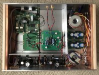
Attachments
Last edited:
Well, I figured I’ll work on what I can.
I read several times that wire wound resistors were preferred in i/v stage applications.
As mentioned, Ryan suggested trying the i/v resistors on the primary side of transformers first.
My understanding is that resistors used on the primary side can impact the sound quality more.
He and others mentioned good results with using Constantine wire to wind their own resistors.
Recently some more of what I read seemed to point towards using a lower value than I had installed which was mk132 paralleled to present 110 Ohms.
Actual impedance measured at the output of my D3 boards with my DVM when powered off was 55 Ohms. I am thinking this may be due to other resistors mounted on the bottom of the board related to the voltage injection Ryan mentioned?
Anyway, I had used the 110 Ohm value because of a post I read by ecdesigns outlining what they would use in a fully passive i/v stage:
“If I -had- to make a -fully- passive I/V stage for the TDA1541A I would do following:
1) Resistive divider that provides +240mV. For example 24 Ohms in series with 476 Ohms connected to the +5V supply and a suitable electrolytic cap (1000uF/6V3 for example) in parallel with 24 Ohms.
0.002mA bias current results in 240mV drop across a 120R resistor. Without further action we would end up with -0.24V DC offset on the I/V resistor and on the connected transformer. By lifting the I/V resistor GND reference to +0.24V this DC offset voltage is nulled (-0.24V) + (+0.24V) = 0. And this can still be achieved with passive components (2 resistors and a capacitor).
2) Connect a 120R Welwyn W21 wire wound resistor between +240mV and TDA1541A output. With TDA1541A full scale current of 4mA this results in 480mVpp. This is still below the clipping limit of around 600mVpp and distortion stays below the audibility threshold of roughly 1%. It is -very- important to use a low noise wire wound (not bulk metal foil !!) resistor here. Welwyn W21 and Rhopoint econister are recommended.
3) Connect a good quality 1:4 step up transformer to the 120R resistor (LL1674 for example). Use a transformer that works optimal with a source load of around 100 … 200 Ohms.
4) Connect a RC filter to the transformer secondary to suppress ringing (use test signal and scope to tune).
You will then have a fully passive I/V stage that provides 1.92Vpp and an output impedance of approx. 1900 Ohms (120R * 4 * 4).
Low passive I/V resistor values give lowest distortion but poor resolution as most of the LSBs are burried deep below the noise floor.”
I don’t think I understand enough of what is suggested to mimic all of what is outlined.
Regardless, I figured I might try a lower value.
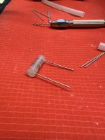
While I try to figure things out with the signal routing and transformers I took a shot at winding my own resistor. I figured I’d shoot for a 50 Ohm resistor.
I’m working with some Constantine wire that is 40AWG and stated to have resistance of just under 30 Ohms per foot.
I did a little math and came up with just over 20 inches of wire.
I built the resistor using some rigid plastic water supply tubing, left over component legs and a hot glue gun.
I managed to come up with a 51.7 Ohm resistor…inside a 5% tolerance.
I’m not sure the exact resistance value matters as much as being able to produce a second resistor for the other channel that matches it as closely as possible.
I read several times that wire wound resistors were preferred in i/v stage applications.
As mentioned, Ryan suggested trying the i/v resistors on the primary side of transformers first.
My understanding is that resistors used on the primary side can impact the sound quality more.
He and others mentioned good results with using Constantine wire to wind their own resistors.
Recently some more of what I read seemed to point towards using a lower value than I had installed which was mk132 paralleled to present 110 Ohms.
Actual impedance measured at the output of my D3 boards with my DVM when powered off was 55 Ohms. I am thinking this may be due to other resistors mounted on the bottom of the board related to the voltage injection Ryan mentioned?
Anyway, I had used the 110 Ohm value because of a post I read by ecdesigns outlining what they would use in a fully passive i/v stage:
“If I -had- to make a -fully- passive I/V stage for the TDA1541A I would do following:
1) Resistive divider that provides +240mV. For example 24 Ohms in series with 476 Ohms connected to the +5V supply and a suitable electrolytic cap (1000uF/6V3 for example) in parallel with 24 Ohms.
0.002mA bias current results in 240mV drop across a 120R resistor. Without further action we would end up with -0.24V DC offset on the I/V resistor and on the connected transformer. By lifting the I/V resistor GND reference to +0.24V this DC offset voltage is nulled (-0.24V) + (+0.24V) = 0. And this can still be achieved with passive components (2 resistors and a capacitor).
2) Connect a 120R Welwyn W21 wire wound resistor between +240mV and TDA1541A output. With TDA1541A full scale current of 4mA this results in 480mVpp. This is still below the clipping limit of around 600mVpp and distortion stays below the audibility threshold of roughly 1%. It is -very- important to use a low noise wire wound (not bulk metal foil !!) resistor here. Welwyn W21 and Rhopoint econister are recommended.
3) Connect a good quality 1:4 step up transformer to the 120R resistor (LL1674 for example). Use a transformer that works optimal with a source load of around 100 … 200 Ohms.
4) Connect a RC filter to the transformer secondary to suppress ringing (use test signal and scope to tune).
You will then have a fully passive I/V stage that provides 1.92Vpp and an output impedance of approx. 1900 Ohms (120R * 4 * 4).
Low passive I/V resistor values give lowest distortion but poor resolution as most of the LSBs are burried deep below the noise floor.”
I don’t think I understand enough of what is suggested to mimic all of what is outlined.
Regardless, I figured I might try a lower value.
While I try to figure things out with the signal routing and transformers I took a shot at winding my own resistor. I figured I’d shoot for a 50 Ohm resistor.
I’m working with some Constantine wire that is 40AWG and stated to have resistance of just under 30 Ohms per foot.
I did a little math and came up with just over 20 inches of wire.
I built the resistor using some rigid plastic water supply tubing, left over component legs and a hot glue gun.
I managed to come up with a 51.7 Ohm resistor…inside a 5% tolerance.
I’m not sure the exact resistance value matters as much as being able to produce a second resistor for the other channel that matches it as closely as possible.
Attachments
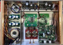
Done…I figured since I wrote a novel to myself I might as well have a happy ending 😁
Thanks to bisesik and all his patience and feedback in the DAC transformers thread.
I now have a beautiful sounding DAC…with as much gain as I could need…and it sounds much better than my old Rotel RCD855 that started this journey when it gave up the ghost several years ago.
Revisions were:
Rewire I2S to Simultaneous and D3 boards for balanced/differential signal transfer.
Replace iv resistors with hand wound Constantine 25 Ohm resistors.
Pull iv resistors from secondaries on transformer boards.
Rewire D3 output to transformer connections for differential/balanced signal.
Only troubleshooting was with the jumpers at J11 & J12. Had them wrong first time around which caused buzzing (thanks again bisesik!)
Attachments
Yes indeed Constantan…pesky auto correct…I ordered some a while back off of fleabay.
After bisesik helped me do some calculations, I decided to lower the value I wound based on what voltage I thought was needed to work with my system.
The 25 Ohm value seems to have gotten me there while helping keep THD in check.
After bisesik helped me do some calculations, I decided to lower the value I wound based on what voltage I thought was needed to work with my system.
The 25 Ohm value seems to have gotten me there while helping keep THD in check.
- Home
- Group Buys
- DIY TDA1541A PCB "D3"