from the number of turns you make me believe that you gonna use an ungaped core ????? the switching transistor will blow-up instantly, due to the inductor saturation. however, 7 turns on ungaped EE55 cannot give you more than 300-400uH. Al=6-8uH/ts2.
consider using a kool-mu toroid, at least one 0077083A7 for this power level.
Keep in mind that that is for L1 which is the common mode input choke for the EMI filter
 so i assumed that is the PFC inductor. if is the common inductor, what's the value and what core have you used for the PFC inductor ? anyway, EE55 for a common inductor is way too big. you should use a small hi-perm toroid, 26 or 31 mm diameter.
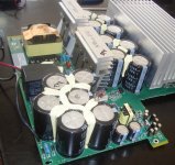
9kw with only 100kHz? I would think that is a bit low, even for that core
I think 10KW should no problem with this core.but circuit only like HB ,not HB .some high power high efficiency brand proamp use this circuit.
Last edited:
Well I have some time to dive back into this project. I am going to draw up the PFC schematic and pcb in eagle.
Can someone please help me source inductors that will work in this circuit.
L1 - Common Mode Input Filter
L2/L3 - Differential Mode Input
L4 - PFC
I dont mind doing windings if I can source the proper magnetics to wind on.
Can someone please help me source inductors that will work in this circuit.
L1 - Common Mode Input Filter
L2/L3 - Differential Mode Input
L4 - PFC
I dont mind doing windings if I can source the proper magnetics to wind on.
hi crazifunguy,
don't bother too much in trying to simulate the common mode inductance value. There are plenty of things that are strictly layout dependent. Normally common mode chokes are designed in a very simple way: pick a toroidal core with high permebility of reasonable size (25-30mm diameter or so), pick a wire of suitalbe cross section for your input current (1.5mmq will be ok). Wind the two sides of the common mode choke only on one layer to minimize intrawinding capacitance.
Wurth has a broad range of ready made cmc, the xl series can fit your requirements.
I suggest to keep the place for two cmc and providing also the place for an x2 capacitor between the two and two y2 capacitors to gnd.
Differential mode choke: use an iron powder core, micrometals material 26 will be ok. It is allowed to partially saturate that core since even at saturation there will be enough remaining inductance. if your pfc is continuous mode (and I hope it is at that power) input ripple is not so high and maybe you can also live without the differential choke, just using the leakage inductance of the cmc. If you run in interleaved it is even better (the input ripple partially cancels out).
Pfc choke: it will be very hard to find something already made on the market. You need to wind it by yourself. You need to know your frequency, your peak current and your inductance value to design it. As first guess I suggest a core not smaller than an etd49 or a kool-mu toroid core of comparable ae.
@authxl: 9kw from a ee55 core?? At 100khz ??? Using sg3525 ????? Maybe with 20% efficiency is possible..... Please be serious; if you can get 3kw from that core in phase shifted full bridge you are lucky...
hi crazifunguy,
don't bother too much in trying to simulate the common mode inductance value. There are plenty of things that are strictly layout dependent. Normally common mode chokes are designed in a very simple way: pick a toroidal core with high permebility of reasonable size (25-30mm diameter or so), pick a wire of suitalbe cross section for your input current (1.5mmq will be ok). Wind the two sides of the common mode choke only on one layer to minimize intrawinding capacitance.
Wurth has a broad range of ready made cmc, the xl series can fit your requirements.
I suggest to keep the place for two cmc and providing also the place for an x2 capacitor between the two and two y2 capacitors to gnd.
Differential mode choke: use an iron powder core, micrometals material 26 will be ok. It is allowed to partially saturate that core since even at saturation there will be enough remaining inductance. if your pfc is continuous mode (and I hope it is at that power) input ripple is not so high and maybe you can also live without the differential choke, just using the leakage inductance of the cmc. If you run in interleaved it is even better (the input ripple partially cancels out).
Pfc choke: it will be very hard to find something already made on the market. You need to wind it by yourself. You need to know your frequency, your peak current and your inductance value to design it. As first guess I suggest a core not smaller than an etd49 or a kool-mu toroid core of comparable ae.
@authxl: 9kw from a ee55 core?? At 100khz ??? Using sg3525 ????? Maybe with 20% efficiency is possible..... Please be serious; if you can get 3kw from that core in phase shifted full bridge you are lucky...
I agree mag, that core wont give even 3KW @ 100KHz, EE55? what a joke, its Burst maybe. But for those who copy things, they dont care.
- Status
- This old topic is closed. If you want to reopen this topic, contact a moderator using the "Report Post" button.
- Home
- Amplifiers
- Power Supplies
- DIY SMPS - PFC/DC-DC