AndrewT -
"I have no idea how quickly the overcurrent can be detected and how quickly the shorting can be applied. But I have a feeling that the output stage will already have passed that overcurrent incident before the fuse can rupture."
But the point is that the time to blow fuse won't be that critical, because while the fuse is deciding to blow the triggered SCR is holding the rectifier output voltage to ground, thus protecting all following circuitry including regulator - until the fuse blows...
Last edited:
Allright, I'll rephrase that:
I have no idea how quickly the overcurrent can be detected and how quickly the shorting can be applied. But I have a feeling that the output stage will already have passed that overcurrent incident before the shorting method can activate and pull the supply down to near zero.
I have no idea how quickly the overcurrent can be detected and how quickly the shorting can be applied. But I have a feeling that the output stage will already have passed that overcurrent incident before the shorting method can activate and pull the supply down to near zero.
I don't know either whether the SCR would be reliably fast enough to protect other semiconductors. But over decades I have been using a circuit like this to protect against regulator failure putting unregulated voltage into rest of circuitry, and it never let me down (at the time I was having problems with a disastrously unstable regulator circuit that put 20V into 10V circuitry if it went s/c, and I needed the protection while I sorted it out - saved me no end of 2N3055s!).
Hi,
This method of crowbar the output voltage was used in computers high current power supplies. It works by shorting the output and force the fuses to blow. This action will protect the computer logic board from high voltage. Some of the boards will costs over 20K dollars.
This method of crowbar the output voltage was used in computers high current power supplies. It works by shorting the output and force the fuses to blow. This action will protect the computer logic board from high voltage. Some of the boards will costs over 20K dollars.
I don't know either whether the SCR would be reliably fast enough to protect other semiconductors.
Fast enough, but not good solution, because You have to replace the fuse after any short overload....
Sajti
Hi,
It is true but it is better than replace the speakers.
I think we have a misunderstanding. The crowbar is good protection against DC output, this protect the loudspeaker. But You need to protect the amplifier against the overload, not the speaker.
I/V limiter would be much better solution! Fast and reset itself if the overload ending.
Sajti
bgw750 was the first amp i saw using scr crowbars...https://www.hifiengine.com/manual_library/bgw/750.shtml
Hi,
In the way they are doing it is possible to damage the output transistor by grounding it to ground. I think it should be doing it at the rails not at the output transistors.
This protection comes to live only if significant DC detected on the output. It usually means, that the output devices are dead.
Sajti
Hi,
If you install the fuses from the PS feeding the rails and the crowbar after the fuses you will protecting also the amplifier.
Yes. But I still feel, that it's not a proper way to protect against overload. There are many better way for that. This is good to avoid the output relay, and protect the speakers against the excessive DC.
Sajti
I agree. One output transistor blew and caused DC on speaker. A crowbar triac from speaker hot to return can blow the other nine. I have an amp with a triac crowbar where the main breaker never blows, just the output devices blow one by one at $5 a pop until they are all gone. Then the current surge out the base line blows 114 other parts.Hi,
In the way they are doing it is possible to damage the output transistor by grounding it to ground. I think it should be doing it at the rails not at the output transistors.
I'm installing rail disconnect nfets to stop DC when DC on speaker is detected. Flirting with idea of using the current across the rail nfets to cause the protection latch to trigger - the current across them when dangerous causes more than 0.7 v drop. Don't know how much integrator I need to prevent nuisance trips. 2 ohm load is valid for this amp, so that is 22 amps.
Last edited:
Can't help thinking a CT monitoring rails and then triggering a safe load sink would be the 'kind' way to unload.
But on speaker protection circuitry [DC and on/off thump] are there any ideas why pin 1 of the uPC1237 doesn't seem to be used in any of the kit or built boards available out of Asia?
Simple enough circuit but needs to be tuned for specific amps for that trip threshold I suppose.
All the boards I find on .au site [includes International listings, admittedly filtered to only venders who ship OS] of that type seem to omit the subject O/L input now.
But on speaker protection circuitry [DC and on/off thump] are there any ideas why pin 1 of the uPC1237 doesn't seem to be used in any of the kit or built boards available out of Asia?
Simple enough circuit but needs to be tuned for specific amps for that trip threshold I suppose.
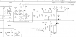
If you go to ebay and search for "30A Speaker protection board DIY Kit including 7812" you will find it. There are a few folks selling it. The one I bought is item #221255947264.
Thanks Terry
All the boards I find on .au site [includes International listings, admittedly filtered to only venders who ship OS] of that type seem to omit the subject O/L input now.
OK, without circuit for O/L signal from emitter resistor node thats looking similar to what I have drafted up. Pretty simple device to connect.
However, my use is for mono [subwoofer amp] and I'll use 2 relays to double break speaker circuit.
Why use 2x of the uPC1237 and associated components?
Thats adopting an industrial use of AC switchgear for DC load breaking.
eg. 415VAC 3 phase - 2500A load break switches or programmable trip curve Air Circuit Breakers are far cheaper to buy and source than 220VDC 2 pole - 2400A switchgear.
For DC I've used 2 of the 3 poles connected in series [+] and the 3rd single break [-]. CT's and VT for line monitoring are modified as DC use specific rather than the standard AC components in these large circuit breakers. This is reasonably large heavy industrial applications for DC motor cranes and essential services distribution/MCC switchboards.... generation facilities.
Anyhow, this is what has me thinking of how we would do this in heavy industry... in the generation/distribution/HV feeder protection fields.
The basic info in the field comes from CT's and VT's that input to very user specific microprocessor controlled protection relays that trip High Voltage CB's... Power factor is another derived input to the logic circuit.
Mind you, that HV could be 2.2kV up to 500kV in a large switchyard... and a 'cascade protection event' could take out half the East Coast in Australia within milliseconds, starting with a cruddy old private consumer main switchboard short circuit fault [say a normally rated 500A supply but having a huge
prospective fault current well over 1000kA] located next door to large terminal substation - very low transmission line impedance.
Has happened, Been there, done that rebuilding thing, messy, but it's impressive to see a 2mm thick copper/steel alloyed and sprayed over a 2 sq metre area onto a brick wall.... kinda pretty iridescent blue/brown/red/yellow coloured effect fully vitrified into the brick surface.
Fugitive 'magic smoke event'... NOT.
Yeah... an audio Amp is DC supply rails but it's an AC signal going to those expensive drivers.... until.
I'd say at DIY/domestic/commercial level the challenge is to design an apt predictive fault discrimination, that obviously doesn't just look at voltage and current. I'd say some form of 'fuzzy logic', auto tune derived load/supply characteristics determined under installation setup testing and clearly defined limits.... and then the basal 'shortcircuit fault' would look very different to a hard driven near O/L transient condition that can be dealt with via gain control rather than rude brutal scr load shed to ground [ouch for those cap's].
Auto tune chips for the likes of pyrometers are pretty common now and used in highly dynamic reactive process control systems... why not look at the same principal given this is also a dynamic load?
So, simple form without serious microprocessor protection monitoring.... perhaps basic line/load impedance variation/discrimination may be useful in telling the difference between chit and clay.
- Home
- Amplifiers
- Solid State
- diy short circuit protection