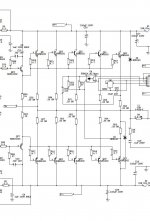
LEACH amp with 9 pairs what output transistors do you plan to use
I am not building a Leach amp, just copy the current limiting circuit. I plan to use TTC5200 and TTA1943 that has 140p and 240p input capacitance resp. It's only 150W transistor but I don't think it's a problem with 9 pairs.
It's not cast in stone by any stretch. It's more at talking stage. I am doing it very slow.
Last edited:
Because to be effective as protection, a wire fuse must be rated very close to the maximum power rating and at that point, it will be heating and cooling rapidly, distorting the output. See "fuse distortion" https://books.google.com.au/books?i...6AEIUDAL#v=onepage&q=fuse distortion"&f=false
'Seems mosfet, you couldn't resist coming back for more.
This is not true !
This is a lie.
cooling and heating.. ok they heat and cool but thats no difference, how that can affect the output ? this is absurd.
distorting.. not true.
show me two snapshots with distortion analyzer showing that, proving it.
On another hand this heating will be not big at all.
Yes i cant resist, but trying.
I am not building a Leach amp, just copy the current limiting circuit.
Read Michael Kiwanuka's article on VI limiters. You'll find it on Bonsai's site.
Brian
Read Michael Kiwanuka's article on VI limiters. You'll find it on Bonsai's site.
Brian
I went to hifisonic site, I can't find that. I looked at his schematic, he use an opto. You draw enough current across the two resistors to turn on the LED to do current limiting. I don't want any complicate stuff like his protection circuits.
Thanks
Attachments
Last edited:
Mosfet, it is your turn prove the evidence of Douglas Self is wrong. Perhaps you can't see the extract of his handbook I posted where the single graph shows the distortion before and after a fuse. For others who have read one edition or another of Audio Power Amplifier Design Handbook, I'm sure you've all seen the graph anyway. You can also Google the extract for yourself. as "fuse distortion"This is not true !
This is a lie.
cooling and heating.. ok they heat and cool but thats no difference, how that can affect the output ? this is absurd.
distorting.. not true.
show me two snapshots with distortion analyzer showing that, proving it.
On another hand this heating will be not big at all.
Yes i cant resist, but trying.
Just be careful who you call a liar when the evidence is available to you and you simply refuse to accept the science. We aren't all kids here who just finished highschool, so quit the tantrum and show your evidence to the contrary.
@ StephenR
Here is a link to Michael Kiwanuka's Paper on SOA limiters - hosted by Bonsai. I admit, it wasn't easy to find it.
Michael Kiwanuka: SOA Protection for Audio Power Amplifiers
Here is a link to Michael Kiwanuka's Paper on SOA limiters - hosted by Bonsai. I admit, it wasn't easy to find it.
Michael Kiwanuka: SOA Protection for Audio Power Amplifiers
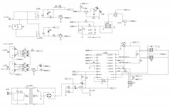
I allways do 2 steps of protection. The first is limiting the output current as a common V/I limiter, and I apply 2nd step, to trigger the relay driver circuit, if the overload exist longer time. This gives instant protection, and time to cool down the output devices.
Sajti
Sajti
I admit, it wasn't easy to find it.
?? Insert Kiwanuka in "Search this site", hardly difficult.
Mosfet, it is your turn prove the evidence of Douglas Self is wrong. Perhaps you can't see the extract of his handbook I posted where the single graph shows the distortion before and after a fuse. For others who have read one edition or another of Audio Power Amplifier Design Handbook, I'm sure you've all seen the graph anyway. You can also Google the extract for yourself. as "fuse distortion"
Just be careful who you call a liar when the evidence is available to you and you simply refuse to accept the science. We aren't all kids here who just finished highschool, so quit the tantrum and show your evidence to the contrary.
This is with FB connected before the fuse, I mentioned that.
connect it after it and voala.
This is with FB connected before the fuse, I mentioned that.
connect it after it and voala.
Some people don't do GNFB. Pass Stasis being one that are famous to name one.
Also, as frequency goes up, loop gains goes down, NFB start to loose control.
@ StephenR
Here is a link to Michael Kiwanuka's Paper on SOA limiters - hosted by Bonsai. I admit, it wasn't easy to find it.
Michael Kiwanuka: SOA Protection for Audio Power Amplifiers
Thanks Ian. It's a long paper.
I allways do 2 steps of protection. The first is limiting the output current as a common V/I limiter, and I apply 2nd step, to trigger the relay driver circuit, if the overload exist longer time. This gives instant protection, and time to cool down the output devices.
Sajti
I thought about this, but I decided against it because it will kick in and out. When you detect over current, relay open, current drop, relay closes, over current, relay opens........... That's the reason I use 2 step to first avoid inrush of huge current using circuit from Leach to limit the max current to like 3 to 4A. Then let the rail fuse do the job and open it.
I do have SS relay to cut the speaker, but mainly for protecting the speaker if DC exist at the output of the amp.
When you detect over current, relay open, current drop, relay closes, over current, relay opens...........
Of course no! I use optocoupler to discharge the capacitor in the turn on delay circuit. This is very comfortable solution, and can be implemented into any existing amplifier, which contains the commonly applied V/I limiter.
It discharge the capacitor in about 0.5sec in case of short circuit. Relay turns off, and the delay process started again. I choose it to 5-6 sec, to give enought time to cooling down the output devices.
Sajti
")
@ StephenR
Here is a link to Michael Kiwanuka's Paper on SOA limiters - hosted by Bonsai. I admit, it wasn't easy to find it.
Michael Kiwanuka: SOA Protection for Audio Power Amplifiers
The transistor is very bad works as a threshold element. The transistors in almost all such protections is not cut off completely, and work with currents of approximately micro - and nanoampers. The output of such protection is typically connected to a point of high impedance, so the non-linear changes in micro - and nanoampere currents of the transistors of the protection make a significant distortion in the amplified signal.
- Home
- Amplifiers
- Solid State
- diy short circuit protection