Not drilled.
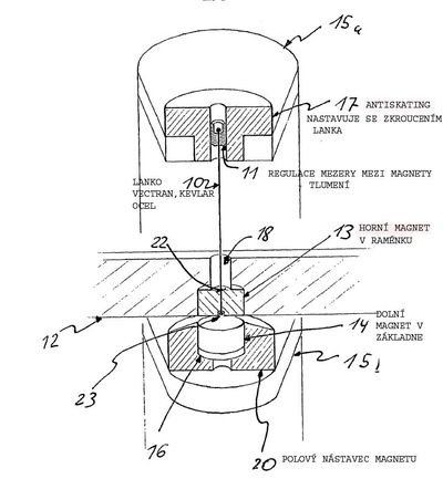
So Herr Schroeder patent application drawings are wrong then?
That's something from the last century.
Hello stoN_Cold,
From what century are you?
")
Ralf
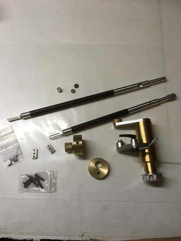

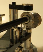
Some progress .... parts now machined... now for the final assembly.
Two arms made ... 9.5 and 11.5 ... we will see which works best on my deck.

Beautiful.
Hi guys,
Just a few remarks, - no DIYer who has put a lot of time and effort into making a tonearm(or whatever) deserves a comment such as "fugly". This is obviously not helpful in a technical sense and since the level of impoliteness is soaring to new heigths everywhere else in today's society, why not just keep quiet if your approval of someone elses sense of aesthetics(or ability to execute his ideal) doesn't match yours.
Btw, I do not rely on any subcontractor for Ref-arm parts, so we're in the same boat. My machine tools might be on a higher precision level than most, but that just saves time and makes for greater repeatability/consistency. A good machinist can produce precision parts on a cheap chinese lathe if he knows his stuff.... it just isn't as much fun
The patent drawing shown does not represent the current standard, but will allow for such an arm to be built successfully if executed properly.
Have a relaxed weekend,
Frank
Hi guys,
The patent drawing shown does not represent the current standard, but will allow for such an arm to be built successfully if executed properly.
Frank
What does the "current standard" involves?
Did it fixed the restoring force issue and the unstable anti-skating force?
Hi Konstantin,
It didn't "fix" the restoring force issue, the currect bearing dimensions/magnet shape results in zero(or near zero) restoring force in the vertical plane and an even higher restoring force(stability) around the headshell - cog of counterweight axis.
Sorry, no idea what you mean by "unstable antiskating". Skating force varies between 4 and 18% of VTF, depending upon many factors, so if anything is unstable, it is skating force
Cheers,
Frank
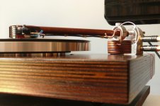
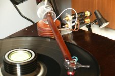
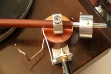
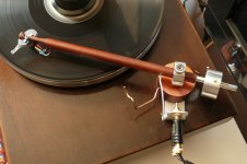
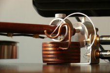
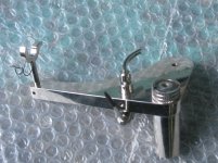
Hi all, this is my project based on Schröder concept. It's very rough, I builded it only for test and compared in this first (very poor) implementation, it sound better than my Rega RB250… I think that I'll rebuild it with better precision. Now it doesn't works properly, VTF change easily and if I beating on plinth, woofer moves. But, with help of this wonderful thread, now I the necessary knowledge to make something better.
Thanks All, specialy to Berlinta,
Corrado
Thanks All, specialy to Berlinta,
Corrado
Attachments
Hi Jeff,
@Bill
Flat cylindrical polepieces of ample thickness(avoid saturation!) will increase the attraction/flux line density on the opposite side by a factor of ~1.3
By using a different layout, this factor can be increased to 7.5 for circular magnets and 18(!) for flat, rectangular magnets.
I'll be of to the RMAF in Denver Monday, so soon I won't be able to reply for about three weeks(sorry).
Have fun guys,
Frank
Hi Frank, I just wanted to ask for confirmation about those numbers. I have been playing with FEMM and using cylindrical pole pieces of either annealed iron or mumetal with the same diameter as the magnets I see no more than 8% increase in the flux density B at the centerline between the two magnets. Is there maybe a particular way to set up FEMM for this kind of problem that a newb might miss? I am using an axisymmetric model with an open boundary.
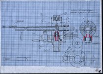
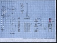
I think you should try this version. It's way easier to adjust.
I haven't seen that design before. I can see the allure of trying to add an adjuster, however, the freedom you introduce in the short horizontal axis places a larger burden in matching the adjuster holes with the hole for the magnet (which appears to be a potted magnet with mounting threads?). Adjusting that thing looks like trying to fly a helicopter.
Hi Frank,
Firstly, thank you for sharing your design with the community. People like you make the world a better place.
Regarding drilling the hole on the top magnet. Just my opinion, the hole is just an unnecessary evil to facilitate changing of the braid line in the future, am I correct? So this means for the DIYer, this hole would not be necessary as we can always make another arm in the future if the line breaks.... ?
Advanced thanks.
Hello gentlemen,
I hope I'm not overly late as I only check this thread when diyaudio sends a notification...
EAlex arm appears to be much closer to the Exact tonearm, based on Mr. Tietze's patent from the 80s, just upside down and with a little bit of Well tempered arm(two suspension threads) added to the mix. I see no reason why this one shouldn't work well, despite the potential issues with such a design.
@skyraider. The above design does not require drilling/polishing any holes for the suspension thread, so it's DIY friendly. I you intend to test various threads and need to exchange the thread frequently, it would be better to run the thread over a defined notch("attachment point"), which also needs to be centered relative to the lower magnet.
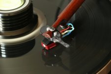
Which brings me to Corrado's arm. nice first attempt, but there is no provision for said centering, so your Azimuth and VTF are most likely to change over the radius of the record. You need to address that in your next implementation.
Have a great weekend,
Frank
I hope I'm not overly late as I only check this thread when diyaudio sends a notification...
EAlex arm appears to be much closer to the Exact tonearm, based on Mr. Tietze's patent from the 80s, just upside down and with a little bit of Well tempered arm(two suspension threads) added to the mix. I see no reason why this one shouldn't work well, despite the potential issues with such a design.
@skyraider. The above design does not require drilling/polishing any holes for the suspension thread, so it's DIY friendly. I you intend to test various threads and need to exchange the thread frequently, it would be better to run the thread over a defined notch("attachment point"), which also needs to be centered relative to the lower magnet.
Which brings me to Corrado's arm. nice first attempt, but there is no provision for said centering, so your Azimuth and VTF are most likely to change over the radius of the record. You need to address that in your next implementation.
Have a great weekend,
Frank
- Home
- Source & Line
- Analogue Source
- DIY Schroeder Tonearm???