I find I'm becoming confused about which mechanisms cause distortions and which cause resonances. I went back to Gerrit's very nice data:
How should the graphs be interpreted?
My initial interpretation of the first plot (lowest tension) is that there is a strong resonance at about 2800 Hz. This shown by the squiggle in the frequency response graph and the pronounced ridge in the waterfall plot.
There are also large second and third order harmonic peaks at 2800 Hz. Those are 2800 Hz outputs excited by input signals at ~1400 Hz and ~930 Hz (one half and one third of 2800 Hz), correct?
When a bit of tension is added to the ribbon (the middle set of plots) the most pronounced third harmonic peak shows up around 1600 Hz. It's quite large, and would be excited by an input signal at 1600/3 Hz = ~530 Hz.
Are the resonances at 2800 Hz and 1600 Hz strongly excited when driven directly at those frequencies (2800 Hz and 1600 Hz)? Excited when driven by 1/2 and 1/3 of those frequencies? Both?
I'm hoping that getting that part straight will help me better understand which mechanisms cause resonances without nonlinear distortion, which cause nonlinear distortion without resonances, and which cause both.
Maybe all this head-scratching will help me stave off Alzheimer's...
Few
Some more test results. A 6µm ribbon with corrugation with just enough tension to flatten the ribbon in the gap, with a little more tension and essentially stretched out. Harmonics and spectral decay are shown:
View attachment 506801
How should the graphs be interpreted?
My initial interpretation of the first plot (lowest tension) is that there is a strong resonance at about 2800 Hz. This shown by the squiggle in the frequency response graph and the pronounced ridge in the waterfall plot.
There are also large second and third order harmonic peaks at 2800 Hz. Those are 2800 Hz outputs excited by input signals at ~1400 Hz and ~930 Hz (one half and one third of 2800 Hz), correct?
When a bit of tension is added to the ribbon (the middle set of plots) the most pronounced third harmonic peak shows up around 1600 Hz. It's quite large, and would be excited by an input signal at 1600/3 Hz = ~530 Hz.
Are the resonances at 2800 Hz and 1600 Hz strongly excited when driven directly at those frequencies (2800 Hz and 1600 Hz)? Excited when driven by 1/2 and 1/3 of those frequencies? Both?
I'm hoping that getting that part straight will help me better understand which mechanisms cause resonances without nonlinear distortion, which cause nonlinear distortion without resonances, and which cause both.
Maybe all this head-scratching will help me stave off Alzheimer's...
Few
There are also large second and third order harmonic peaks at 2800 Hz. Those are 2800 Hz outputs excited by input signals at ~1400 Hz and ~930 Hz (one half and one third of 2800 Hz), correct?
No, the graphs always show the harmonics belonging to the same frequency as the fundamental, you can see that as the graph for the second harmonic stops at 12kHz where the 2nd harmonic is 24kHz, the third stops earlier and so on for the higher harmonics.
The fact that it is the 3rd harmonic that peaks indicates a symmetric non-linearity.
Keep in mind that all distortion graphs have a 1/24oct resolution which is very high for this kind of plot.
regards,
Gerrit
....until somebody showed me how it's done (thank you again for that Peter).
Could you please share how this is done?
//
Could you please share how this is done?
//
It's a fiddly business and I couldn't tell you how to calculate this for a different core and wired diameter. The trick is to completely fill the inner core with wire so as to use as much as possible of the available core. I used a core with 61mm outer diameter, 35mm inner and 12.7mm hight. The wire is 0.6mm. You start with getting 22 windings on the core in parts of 5 or 6 windings. This is the fiddly part, to get all these windings without running out of space on the inside while still filling the inside to the max. Then you glue the wires in place, just enough to keep them in place. Next you remove every other wire and replace it with the primary winding.
Here's another picture of the setup I used for testing the transformer, a 50mΩ resistor is used to simulate the ribbon. Above 1kHz this transformer can deliver 20A into 50mΩ with THD below 0.05%

I hope this helps.
regards,
Gerrit
Thanks for the description Gerrit! Yes it seems complicated.
Which of these magnets would you pick to build a pair of ribbons tweeters similar size as yours?
Block 50x10x4 mm
Dimension: 50x10x4mm / Volume: 2000mmł
NdFeB Magnet in N42 (1.33 Tesla)
Magnetized Direction:*through 4mm
Coating:*Ni-Cu-Ni
Max. Operating*Temperature: 80°C
item # Q-050-010-4-N
56€
Block 35x14x4 mm
Dimension: 35x14x4mm / Volume: 1960mmł
NdFeB Magnet in N42 (1.33 Tesla)
Magnetized Direction:*through 4mm
Coating:*Nickel
Max. Operating Temperature: 80°C
item # Q-035-014-4-N
71€
Block 30x10x5 mm
Dimension: 30x10x5mm / Volume: 1500mmł
NdFeB Magnet in N52 (1.48 Tesla)
Magnetized Direction:*through 5mm
Coating:*Nickel
Max. Operating*Temperature: 80°C
item # Q-030-010-5-N52
60€
The above are from
NEOTEXX m@gnete
Any other supplier/products to recommend in Europe?
Thanks for any answers!
//
These do not have the correct magnetisation direction if you want to make a double magnet construction like I did. I used 50mm x 10mm x 4mm blocks magnetised direction through 10mm. These are custom magnets so I ordered them in N52 strength which is the highest available.Thanks for the description Gerrit! Yes it seems complicated.
Which of these magnets would you pick to build a pair of ribbons tweeters similar size as yours?
Block 50x10x4 mm
Dimension: 50x10x4mm / Volume: 2000mmł
NdFeB Magnet in N42 (1.33 Tesla)
Magnetized Direction:*through 4mm
Coating:*Ni-Cu-Ni
Max. Operating*Temperature: 80°C
item # Q-050-010-4-N
56€
Block 35x14x4 mm
Dimension: 35x14x4mm / Volume: 1960mmł
NdFeB Magnet in N42 (1.33 Tesla)
Magnetized Direction:*through 4mm
Coating:*Nickel
Max. Operating Temperature: 80°C
item # Q-035-014-4-N
71€
Block 30x10x5 mm
Dimension: 30x10x5mm / Volume: 1500mmł
NdFeB Magnet in N52 (1.48 Tesla)
Magnetized Direction:*through 5mm
Coating:*Nickel
Max. Operating*Temperature: 80°C
item # Q-030-010-5-N52
60€
The above are from
NEOTEXX m@gnete
Any other supplier/products to recommend in Europe?
Thanks for any answers!
//
The sketch I used for ordering:
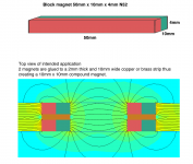
bolserst provided some links to stock magnets with the correct magnetisation direction, see this post
The company Jonas suggested does not do custom jobs anymore, I ordered magnets from them for earlier projects and they do deliver fast.
regards,
Gerrit
OK thanks - I must have misunderstood the term. I thought saying "magnetized through" ment that that side became a pole. As if you wanted your 2 rods to attract so that the 4mm sides meet rather than the the 10mm sides. Apparently not.
But maybe I have misinterpreted the drawing but to me it looks like the 4mm sides are arranged so that a 4mm N face see a 4mm S face with the gap for the ribbon between them.
But I think I do get the drawing.... it jives with how I thought this would work.
Obviously I'm missing something
//
But maybe I have misinterpreted the drawing but to me it looks like the 4mm sides are arranged so that a 4mm N face see a 4mm S face with the gap for the ribbon between them.
But I think I do get the drawing.... it jives with how I thought this would work.
Obviously I'm missing something
//
I've tried to capture the ribbon resonance:
Ribbon resonance
It looks like it is indeed a string like resonance.
regards,
Gerrit
Ribbon resonance
It looks like it is indeed a string like resonance.
regards,
Gerrit
Magnetised through 4mm means that the 10mm x 50mm sides will stick together. Magnetised through 10mm means the 4mm x 50mm sides will stick together, this is what you want. The drawing represents the top view of the magnets as they are mounted in the frame.OK thanks - I must have misunderstood the term. I thought saying "magnetized through" ment that that side became a pole. As if you wanted your 2 rods to attract so that the 4mm sides meet rather than the the 10mm sides. Apparently not.
But maybe I have misinterpreted the drawing but to me it looks like the 4mm sides are arranged so that a 4mm N face see a 4mm S face with the gap for the ribbon between them.
But I think I do get the drawing.... it jives with how I thought this would work.
Obviously I'm missing something
//
You are correct that the magnets are arranged so that the 4mm x 50mm N side sees a 4mm x 50mm S side on the other side of the air gap.
I hope it's more clear now.
regards,
Gerrit
Okey - so it was the through that I misinterpreted. The N/S will go 90deg compared to "through". Does that definition have to do with how the process of magnetization is done?
For me at least it was not intuitive.
Thanks again!
//
I guess it's the convention in this business. I checked this x times before I placed the order
Here's a picture of a stack of magnets:
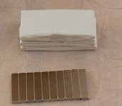
These are 50mm x 10mm x 4mm, the magnetisation is through the 10mm axis. You have to twist these apart, it's impossible to pull one of the stack.
regards,
Gerrit
The field from side to side is not constant! Look at the first post in this thread.
FEMM is a 2D simulation tool!
View attachment 504047
The flux lines crossing the gap are NOT correct as the depth dimension is not taken into account. A separate top view simulation shows what going on:
Would a 3 ply work even better? Say 3-0,6-3-0,6-3
//
No, the graphs always show the harmonics belonging to the same frequency as the fundamental, you can see that as the graph for the second harmonic stops at 12kHz where the 2nd harmonic is 24kHz, the third stops earlier and so on for the higher harmonics.
Got it. Thanks. I didn't notice the frequency limits of the graphs. My measurement software shows the harmonic peaks at their frequency, not the fundamental frequency, so that contributed to my confusion.
Nice video of the resonance! So is the idea that at the resonance frequency the diaphragm is driven out of the more homogeneous part of the field and that causes the nonlinear distortion? Are you seeing harmonic distortion associated with every resonance? Your design nicely avoids major cavity resonances so I'm trying to figure out if you can reliably use harmonic distortion peaks as a sign of ribbon resonances.
Few
Would a 3 ply work even better? Say 3-0,6-3-0,6-3
//
No, I don't think so. The trick is to put the ribbon in the gasp between two magnets, this is the area where the fields of the two magnets push against each other and flatten out. The wider the gap between the magnets, the more even the field becomes but the overall strength declines. This is why I used a 1mm gap between magnets in my minimal ribbon to maximise strength and a 2mm gap with the steel frame ribbon as the closed magnetic structure provides more strength already so I can afford to loose some strength.
Got it. Thanks. I didn't notice the frequency limits of the graphs. My measurement software shows the harmonic peaks at their frequency, not the fundamental frequency, so that contributed to my confusion.
Nice video of the resonance! So is the idea that at the resonance frequency the diaphragm is driven out of the more homogeneous part of the field and that causes the nonlinear distortion? Are you seeing harmonic distortion associated with every resonance? Your design nicely avoids major cavity resonances so I'm trying to figure out if you can reliably use harmonic distortion peaks as a sign of ribbon resonances.
Few
I'm still not sure as to the exact mechanism that the distortion. Previously I tried fixing the ribbon in place using little blobs of silicone grease but this didn't eliminate the distortion.
Yes, every time a resonance pops up there is a distortion peak associated with it.
The video was made with a camera placed on a tripod at the same hight as the microphone, about 50cm behind it and 40cm to the right. You would't believe the effect this has on the spectral decay.
With the camera in place:
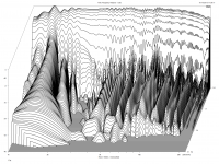
With the camera removed:
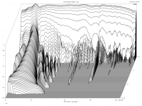
I didn't expect this much influence, it shows why it is import to have a reflection free microphone stand.
regards,
Gerrit
I've tried to capture the ribbon resonance:
Ribbon resonance
It looks like it is indeed a string like resonance.
regards,
Gerrit
The shape of the magnetic return circuit, is that governed by acoustics or by FEMM to get an even field in the gap?
//
The shape of the magnetic return circuit, is that governed by acoustics or by FEMM to get an even field in the gap?
//
A bit of both. The first frame was optimised for an even field in he gap. The hourglass shape is supposed to mitigate the baffle diffraction effects. Beware that the FEMM simulation is only partially correct.
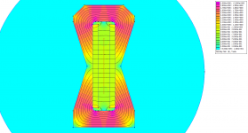
In this view the simulated flux density in the gap will not be correct because FEMM does not take into account the depth (it assumes infinite depth, the depth parameter in de settings is just for force calculations). The flux density at the red line is actually the density at the edge of the gap (more or less). The flux density in the return path will be much more accurate because the field lines pretty much stay in the steel.
There's no way to simulate the double magnet construction in this view, you can only hope to create an approximation.
In the new design I tried to minimise the frame dimensions for better acoustic behaviour, because of the 2mm gap there's 20% more return path hopefully this compensates the loss of return path.
If they weren't so expensive I would have bought a Gauss meter, still thinking about it.
regards,
Gerrit
- Home
- Loudspeakers
- Planars & Exotics
- DIY ribbon dipole tweeter, reductio ad minimum
