Hi there, indeed the Hami 8" is suitable for DIY pj's. It has not yet been tested in a working test setup, however the lcd is cleanly strippable. One issue is that 1 FFC cable needs to be extended. The transparency of the LCD seems to be adequate, however it wasn't compared side by side to the lilliput.
The pricing from the Chinese supplier on ebay is very reasonable at 126 for the model with the TV-tuner. A german webshop for DIY projectors will place an order of 50 units, just to illustrate the trust he lies in the product. He will be offering it for around 160 euro, 209 USD.
I suggest to wait for some results, and make sure the pitfalls are known. (1 is known already, connecting the FFC to the screen the wrong way around will result in the death of the LCD...)
greetz Initial G
Thanks for that information.
I think HAMI is not a manufacturer unlike the LILIPUT but rather a distributor. Here in the Phils. it is being sold as YAJIA with identical specs as HAMI including the appearance. And store retail price is about $126. Maybe we can get a better pricing if we can discover the manufacturer.
I think HAMI is not a manufacturer unlike the LILIPUT but rather a distributor. Here in the Phils. it is being sold as YAJIA with identical specs as HAMI including the appearance. And store retail price is about $126. Maybe we can get a better pricing if we can discover the manufacturer.
Attachments
hertzblaster said:MY PJ!
Dude I seriously think your projector looks WAY better then the dlp530, the coloring is SO much better.

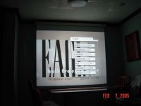
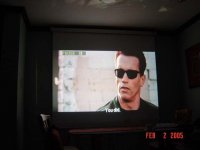
As can be seen in the OSD, Gamma and sharpness is adjustable. For Pioneer DV266, only Brightness, contrast,hue and saturation are adjustable. JVC called their processing as VERSATILE FINE PROCESSOR (vfp)
Here is my initial evaluation
1. GAMMA adjustment is in 3 steps only. Low(default), Med and high. Setting the Gamma to med and HIGh will brighten up the image especaily in dark scene. I rate this adjustment as EXCELLENT.
2. Sharpness setting in 2 steps only. Low and High (default). Just a little useful for me
3. Contrast setting is from -12 to 12. Very good flexibility. What makes this very different with Pioneer DV266 is incresing the contrast will make blacks blacker, the color deaper and more saturated and the best of all , IT INCREASES THE OVERALL BRIGHTNESS unlike the Pioneer DV266 where the total image becomes dim as you increase the contrast. I guess this is the strength of this JVC model.
4.. Brightness adjustment is up to 15. Very good flexibility also.
5. I found the close caption as whiter and brighter than the Pioneer.
6. Pioneer has i guess a slight advantage in image detail and sharpness.
OVERALL, i prefer the JVC because of Gamma and better contrast processing. Image brightness overall is much brighter and color is more saturated than Pioneer Dv266
JVC price is $89
Pioneer DV266- $116
Attachments
JVC's Gamma and contrast adjustment are excellent for movies. I feel like approaching commercial pj brightness.
An externally hosted image should be here but it was not working when we last tested it.
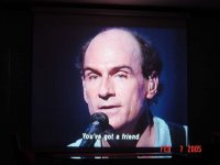
Here is more of JVC has done to my image quality and brightness.
If you think of buying dvd player for your pj, have a second look at jvc model. its much better overall than pioneer.
The dvd btw is highly recommended. its one of my collection now.
If you think of buying dvd player for your pj, have a second look at jvc model. its much better overall than pioneer.
The dvd btw is highly recommended. its one of my collection now.
An externally hosted image should be here but it was not working when we last tested it.


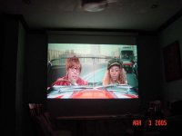
Hot not spot
Hertz,
That light looks extremely even!
I am still sourcing components like condenser lenses...
I asked you the other day about the effect of running an e-ballast at 50 Hertz instead of 60 Htz and you were kind enough to give me the formula showing that there will be 20 volts less across the points of the lamp at 60 Htz in Australia.
My dilemma is this: get an e-ballast that runs 20v under or get a coil ballast.
I seem to recall you were doing some comparative research into running a coil ballast versus e-ballast and you found that the e-ballast was brighter and more efficient.
Do you think you can tell me which is better: to run coil ballast at 240v 50htz or an e-ballast at 240v 60Htz (with a 20v penalty).
Once again I am indebted to you for your expertise. Thanks,
G
Nope,not doing anything about comaparative brightness between e-ballast and EMB. My negotiation with Chinese designer fizzled out.
Just a clarification, i am comparing a 50 hertz rated EMB ballast as against 60 hertz rated EMB when 50hertz mains is apllied. Not an e-ballast as against EMB.
There is an old thread here about comparison of ballast. Try to search for it but i will help you also.
Here is what the Chinese manufacturer told me to do to get the best from the bulb.
" Send me 3 samples of osram Hqi-tsd and we will calibrate the e-ballast base on bulb power requirements "
Sounds great but i can't send 3 bulbs just for testing.
Again, each ballast is designed for a partiicular bulb.
BTW my ballast right now is made from AUstralia. I got 90 v across the bulb but luckily, i have a variable voltage regulator where i can up the voltage easily to get maximum output from the bulb.
As far as i can remember, in some test comparison in some site, they are running it 130v across the bulb which way is beyond bulb volatge requirement.
Generally, the electric ballast ( as in any elecric aplliance ) can tolerate 10% overvoltage but is not always a guarantee that it may not cause damage or gives a shorter life. A 30% overvolatge i guess is too much.
An externally hosted image should be here but it was not working when we last tested it.

Theoretically, eballast should give u a better lumen output because of absence of flicker. I have not compared it myself but here again is the link for comparison of DE bulb running with different ballast.
http://www.advancedaquarist.com/issues/feb2004/feature1.htm
http://www.advancedaquarist.com/issues/feb2004/feature1.htm
Bite the bullet
Hertzblaster,
Thanks for link. I forgot about that one - you linked me there some time ago but my memory is not as good as it used to be.
I have decided to go with the electronic even though it will be 20 volts lower than it should be.
As you say, there will not be flicker and also, importantly to me it will run cooler.
If it runs quieter, than that is a true bonus as it stands a better chance of approval from as you say, the "Commander in Chief".
Cheers,
G
Try to check if the eballast that you are to buy can be calibrated. I think it can be adjusted to give you the right power output.
Do this right and and you get bright projection..
Do this right and and you get bright projection..
An externally hosted image should be here but it was not working when we last tested it.
a balast will try to ouput a consistent wattage ...... Power (watts) is equal to the current multiplied by the voltage.
If for any reason there is a voltage drop, then the ballast should SINK more current through the bulb to maintain the proper wattage, however there is a point when TOO much current will be drawn. If there is a drop in voltage then if anything the ballast will run hotter due to the current increase ... however I think that It will run at approximatly the same temp because no matter what your still dissapating a fixed wattage of either 250W or 400W.
I didnt read the whole thread, so Im unceartain as to HOW, or WHY you want to run a 60Hz ballast on a 50Hz system, (unless you are assuming the use of a wall converter)
none the less, you can get E-ballast in both the 120V 60Hz flavor or a 240V 50hz flavor on the Lumenlab Website
good job on your Pj hertz ..... This thread was entirely to long for me to read, but I clicked through it and watch the progress of you pics ....
What is your final setup ... did you transition to 400W ..... Did you transition to a split fresnel, and how big is your screen??
scubasteve2365,
Nice results! ! If only big box is not a problem for me, i could be one of the guys at lumenlab.
To be more precise,
Power ( watts ) = voltage x current
This formula is true for direct current where power factor is equal to 1
Power (volt- amperes ) = voltage x current
Volt-ampere is the unit when you multiply voltage by the current for alternating current application
Power (watts ) = voltage x current x power factor
This is the correct formula for computing power in watts for alternating current.
To get the power factor, you will need to get the power factor meter.
I used to know how to compute this power factror mathematically but i already forgotten it.
my conclusion is , its hard to get real power dissipation of the bulb unless you know the power factor. Power factor can go as low as 50% for misapplication. Just because you have a capacitor installed doesn't mean you can get 90% power factor as advertised. never assume that you can get power factor of 1 for alternating current application
But the easiest way to know the real power dissipation of the bulb is to use a wattmeter which i don't have.
In Australia, the mains voltage is 240v @ 50 herts ( correct me if i'm wrong). goemon is asking me if he can use a ballast rated at 240@60hertz. which for him is easily available i suppose.
i use 250w HQI-tsd with 2 condenser lens
DIY reflector
SPlit fresnel set-up
Keystone (severe top fresnel angle) corrected. Image is above the projector when view at the back or at my sitting position.
Screen is Dalite 70x70 , cheapest model, don't know the gain
regards,
Hertz
Nice results! ! If only big box is not a problem for me, i could be one of the guys at lumenlab.
a balast will try to ouput a consistent wattage ...... Power (watts) is equal to the current multiplied by the voltage.
To be more precise,
Power ( watts ) = voltage x current
This formula is true for direct current where power factor is equal to 1
Power (volt- amperes ) = voltage x current
Volt-ampere is the unit when you multiply voltage by the current for alternating current application
Power (watts ) = voltage x current x power factor
This is the correct formula for computing power in watts for alternating current.
To get the power factor, you will need to get the power factor meter.
I used to know how to compute this power factror mathematically but i already forgotten it.
my conclusion is , its hard to get real power dissipation of the bulb unless you know the power factor. Power factor can go as low as 50% for misapplication. Just because you have a capacitor installed doesn't mean you can get 90% power factor as advertised. never assume that you can get power factor of 1 for alternating current application
But the easiest way to know the real power dissipation of the bulb is to use a wattmeter which i don't have.
I didnt read the whole thread, so Im unceartain as to HOW, or WHY you want to run a 60Hz ballast on a 50Hz system, (unless you are assuming the use of a wall converter)
In Australia, the mains voltage is 240v @ 50 herts ( correct me if i'm wrong). goemon is asking me if he can use a ballast rated at 240@60hertz. which for him is easily available i suppose.
What is your final setup ... did you transition to 400W ..... Did you transition to a split fresnel, and how big is your screen??
i use 250w HQI-tsd with 2 condenser lens
DIY reflector
SPlit fresnel set-up
Keystone (severe top fresnel angle) corrected. Image is above the projector when view at the back or at my sitting position.
Screen is Dalite 70x70 , cheapest model, don't know the gain
regards,
Hertz
With all due respect Hertz ....
A Volt-Amp (VA), Is the unit of measurement when calculating Aparant Power ( abreviated as |S| ) ...
Imaginary or Reactive Power (abreviated as Q) is the Power dissapated in frequency dependent components, things like Capacitors and Inductors The unit of Measurement is (VAR .. Volt-Amp Reactive)
Wattage is the terminolgy for REAL POWER (W), and is the power dissapated in resistances ECT.
The power factor, is the ratio of Real Power to Apparent Power ...( W/|S| )
Since All powers can also be found by taking the square of the current times the resistance then .... |S| = I^2 *Zt .. where I is the total Source Current, and Zt= is the total impedance of the circuit ..... and W = I^2 * R (where I is the current through the Resistive components only ..... Leaving you a power factor equation of ... (I^2*R\I^2*Zt) ... the I^2 will cancel each other out ..... and your Left with ... R\Zt ...
you can further manipulate the above equation by breaking the total impedance down to its real and reactive components, where Zt = the square root of (R^2) - (Z^2) .... old pythagoeran formula works for this because your reactive (imaginary) components are 90 degrees out of phase with your input source ..... leaving you with nothing but 90 degree right triangles if you plot each vector indiependently .....
With all of the above said ..........
If you had an 120V AC source going accross a 10kOhm resistor then you would have a Power Factor of 1... A perfect system ... Power factor changes when you add caps/inductors ..... on the premise of how you calculate their impedance. A DC source has a a frequency of 0Hz (obviously0 ... An inductors impedance is found by the following 2(pie) *F*L,where Pie is the old 3.14, f is the frequency (for DC its 0Hz) and L is the Inductance value .... For DC this works out to be 0 (since anything multiplied by Zero is Zero)
therefor a capacitors impedance is 1\2(pie)(f)(C), where Pie is the old 3.14, f is the frequency (for DC its 0Hz) and C is the capacitance value ...... When F= 0Hz you will see that the math works down to 1/0
Algebraicly we were taught that 1/0 = 0 ... however calculus showed us that in alot of situations (electronics being one of them) that 1/0 behaves more like Infinity,
Therefor if you had a DC source feed onto a series connection of a resistor and a capacitor, the capacitor would resist any voltage flucation and become essentially an open, making all of the voltage drop accross it and not the resistor .... Meaning that you would Have NO REAL POWER, but you would have ALL REACTIVE POWER .... Which would also be equal to the APPARENT Power, and the Power Factor would be 0,
So, as Ive layed out .... Power Factors are present in both AC and DC Systems ..... as well as Apparant Power can be present in both AC and DC systems... Nonetheless going back to my first post above without knowing any components I could just edit it to say .... 400VA = I * R, and the Ballast will still try to increase the current in the lack of voltage in order to maintain a consistent power output, regardless of what the Power factor is, the bulb wants to dissipate a certain amount of power, and the ballast will want to give it that amount of power untill the circuit becomes unstable....
BTW .... I graduate soon with My Electrical Engineering Degree from Purdue University, I didnt make any of the above up .... but rather payed a pretty penny for someone to teach it to me ...
Is 240V 60Hz an electrical system somewhere?? ..... I thought it was only 240V 50Hz ..... I live here in the states so I dont pay much attention to other systems ...... Even though I wouldnt try it, for the sake of the life of the ballast .... the ballast probably has some reactive components in it, and this will increase current. The current increase Very well may be safe and stable and the ballast could operate for years to come ..... but ...at the same time the current increase may be toooo much for the ballast, and it might cough out after a few days .... The only way this question could be truely answered properly was if someone looked at the internal components of the ballast.... My guess is that they use a High power Voltage to Current convertor cicruit then run that through a Current to Voltage converter circuit so that you have a perfectly stable 400 (UNITS Either W OR VA) of power coming out. If thats the case you could exceed the power/current threshold of the Op amps or whatever, but again no way of knowing for sure unless I got to see the Ballast's insides ....
Again good job hertz ..... You did alot of trial and error to your PJ to get the screen bright and even .... something Ive battled in the past few months ... You can see my results here ...
http://www.diyaudio.com/forums/showthread.php?s=&threadid=52796
-Scuba-
- Status
- This old topic is closed. If you want to reopen this topic, contact a moderator using the "Report Post" button.
- Home
- General Interest
- Everything Else
- The Moving Image
- DIY Projectors
- diy projector from the Philippines