rmj, you could do a much better circuit layout.
That's no way of using an op-amp.
No PSU caps near the chip?
I wouldn't be surprized if the NE5532 sounds better on this circuit that the OPA2134...
Anyway, for a phono pre with a double op-amp I would go for the OPA2228 instead of the OPA2134.

That's no way of using an op-amp.
No PSU caps near the chip?
I wouldn't be surprized if the NE5532 sounds better on this circuit that the OPA2134...
Anyway, for a phono pre with a double op-amp I would go for the OPA2228 instead of the OPA2134.
Per-Anders, I'm just trying to be constructive and help rjm make a better circuit layout.
Spare two cheap caps doesn't make sense to me, even on a simple design.
And, I've said it several times here, you can ruin the sound of an OPA (or any modern/fast op-amp) just by using it the wrong way.
Believe me.
So... why bother to use an OPA2134 on this circuit?
Gotta tell you a secret: the OPA2228 behaves much better without bypassing.
If you try it on this circuit as it is, it will SOUND much better than the OPA2134.
P-A, is the cable capacitance in series to the cartridge impedance, R+L+C? I would have thought the capacitance is between the input and ground. In any event even 400pF isn't going to make much of a contribution at these frequencies, and pales in comparison to cartridge inductance.
As for the bypass question:
In my view this is not a high frequency circuit. Small signal bandwidth is about a megahertz depending on the gain setting and op-amp used. So "close" to the opamp may be taken in cm rather than mm.
The low impedance electrolytics, which are only 3 cm of straight wire from the op-amp's power pins, should provide good bypassing over the bandwidth of the circuit.
But, just because I don't always trust my own analysis last week I did put 0.1 uF ceramics in the "proper" place next to the power pins of the op-amp.
[I should add that most people seem happy if the cap itself is next to the power pins and don't worry particularely how far away it is to the load return. Be that as it may ... ]
I could, just about, hear a difference, though it was at the limits of my perception. The treble took on a slightly damped, closed in quality. With the caps gone the amp sounded more open and natural, but perhaps noisier.
For now the caps are gone, I think I prefer it this way but I'll keep an open mind while I continue the evaluation of the circuit in general and have a chance to check out how an OPA2134 sounds in there.
-rjm
As for the bypass question:
In my view this is not a high frequency circuit. Small signal bandwidth is about a megahertz depending on the gain setting and op-amp used. So "close" to the opamp may be taken in cm rather than mm.
The low impedance electrolytics, which are only 3 cm of straight wire from the op-amp's power pins, should provide good bypassing over the bandwidth of the circuit.
But, just because I don't always trust my own analysis
last week I did put 0.1 uF ceramics in the "proper" place next to the power pins of the op-amp.[I should add that most people seem happy if the cap itself is next to the power pins and don't worry particularely how far away it is to the load return. Be that as it may ... ]
I could, just about, hear a difference, though it was at the limits of my perception. The treble took on a slightly damped, closed in quality. With the caps gone the amp sounded more open and natural, but perhaps noisier.
For now the caps are gone, I think I prefer it this way but I'll keep an open mind while I continue the evaluation of the circuit in general and have a chance to check out how an OPA2134 sounds in there.
-rjm
rjm, it's more important to have capacitance near the chips than just a 0.1uf cap.
I'd put two small 22~100uf caps between the chip's pins and ground.
If there's no space to bypass with a small one, then don't bother.
The OPA2132, that I know very well (similar to the 2134) has a detached bass, uncontrolled, flappy, dominant, if used on a circuit like you have now.
Treat it as it likes and it will give you a tight, dynamic, detailed presentation, very impressive.
High-end, really.
I talk by experience with these chips.
I mean building and LISTENING experience.
Not just electronics by the book.
My passion is Audio.
BTW to all, take or leave my advice, it's up to you.
To change the subject a little, what do you think of this then?
VSPS Ultra
It's a little extreme, in the early stages, and may yet be consigned to the dustbin - but feel free to chew into it anyway. I'm not too familiar with moving coils, so expect bugs.
-rjm
VSPS Ultra
It's a little extreme, in the early stages, and may yet be consigned to the dustbin - but feel free to chew into it anyway. I'm not too familiar with moving coils, so expect bugs.
-rjm
The value of the caps on the feedback loop is too high...
And I don't understand why you put only 220uf before the regulators.
And why 220uf after the regulators.
Better would be to bypass the regulators' output with a small cap and put the caps where they are needed: AT THE OP-AMP'S SUPPLY PINS.
Does it make this simple design more expensive?
Don't think so.
Just better.
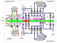
I re-wired the VSPS filter caps as shown on the pic below.
The output from the regulator is wired directly to the IC power pin, and this 220uF cap is no in effect wired directly to the IC power pins too.
Granted the leads are still a bit longer that one might like, but any bypass cap would have to be connected to the load return point (the red oblong on the ground next to R7) so it isn't that bad a compromise.
So we now have the IC "directly" bypassed by a large value cap, as Carlos wanted. Simple experiment:
If I'm right then this connection change will make absolutely no difference in the sound. The circuit is equivalent but for a few cm of wire.
If I hear any difference then I'll have to start paying attention to his posts.
Guess what: pretty big difference. Similar but more significant than when I tried bypassing with the 0.1uF ceramics: less treble energy, less noise. The balance of the music is shifted quite dramatically downwards from the treble to the midrange. This time though the naturllness of tone is retained.
Go figure. I'm going to look at the layout again to see what can be done to tighten up the distances.
-rjm
Attachments
I realise that's what you had in mind.
(Where would we be without MSPaint!)
220uF is sufficient before the regulator to prevent dropouts. I see no point in increasing the conduction angle further by adding capacitance ... been there, done that, sounds bad. Though 2200uF is still borderline ok if you insist.
My main objection is those 47uF bypass caps now create a nice little ground loop indicated by my zigzag line. Noise currents off the power supply are now injected into the op-amp inputs. To prevent that you'd have to take the input grounds back to R2-R7 by a separate wire and that starts getting a bit messy!
Although having the caps physically sung next to the op-amp looks nice and correct, its really a false sense of security. The point the bypass has to get back to is R7. Whether the cap is next to R7 with a lead up to the IC, or at the IC with a lead back to R7, makes no difference to any electrical response.
rjm
Attachments
![vsps_layout_mod[1].jpg](/community/data/attachments/6/6986-8f40395ab3073ef19f6247e35449e71a.jpg)

Konnichiwa,
Yup. Good grounding is NOT easy. It does help to have the supply grounds separated until the star ground and to NEVER use BUS grounding (no matter how tempting). There are several possible neat tricks around this.
I prefer the one where there is only ONE local decoupling Cap between +V and -V instead of the symmerical pair of capacitors. Also consider making the supply lines lower inductance and shorter.
Or you could add some further RC filtering on the supplies, which is definitly good for the sound in more cases than it is not.
Anyway, there are many possible neat options to have clear grounds and layout.
Sayonara
rjm said:My main objection is those 47uF bypass caps now create a nice little ground loop indicated by my zigzag line. Noise currents off the power supply are now injected into the op-amp inputs. To prevent that you'd have to take the input grounds back to R2-R7 by a separate wire and that starts getting a bit messy!
Yup. Good grounding is NOT easy. It does help to have the supply grounds separated until the star ground and to NEVER use BUS grounding (no matter how tempting). There are several possible neat tricks around this.
I prefer the one where there is only ONE local decoupling Cap between +V and -V instead of the symmerical pair of capacitors. Also consider making the supply lines lower inductance and shorter.
Or you could add some further RC filtering on the supplies, which is definitly good for the sound in more cases than it is not.
Anyway, there are many possible neat options to have clear grounds and layout.
Sayonara
Those 47uf caps are there just because the OPA2134 (or similar) NEEDS them.
I'm talking sound quality here. LISTEN to what you do.
Find a way to optimize the layout, but leave them where they are.
If everything is well, the OPA2132 is MUCH SUPERIOR than the OPA2604.
But you have to give it what it likes.
I'm not surprized that some people don't like the 2132.
It's only audio.
(c) Jean-Paul
A star ground, when looked at closely enough, is just a short bus ground and for the beginner often as not turns into a mutant hedgehog with wires poking out every which way from out of a 50g solder ball. And since a few mm can be disastrous, I suggest people first learn enough to be able to wire a bus ground in the right order and then work on making it as small as possible.
For a single non-inverting stage it is really easy:
Front to back, we have: noninverting grounds, inverting grounds, load grounds, bypass grounds, regulator grounds, and power supply grounds. Stick with that and no ground loops will occur even if the power supply grounds or the inputs are shared, as in the VSPS layout.
No ground loops, but lead inductance can be a problem with a long ground bus, just as it is for long lengths of wire in other critical places. So the ground bus has to be as tight as possible between the bypass caps and the load, just as the power lead between the bypass cap and the IC has to be short.
Still the components - espcially through hole - are of a finite size putting a limit to how small everything can be made. And compromises: halving one lead length may more than double another for example.
I'll prioritize the bypass cap lead length and see what can be done in terms of a new layout.
-rjm
Konnichiwa,
If it is THAT then it is NOT a star ground. I usually use multiple star grounds ensuring correct "kelvin returns" (meaning single physically extremely small points where all currents in the relevant loops add to zero) for the local loops. I then "bus" these local stars using low inductance techniques.
Remember, you are in effect amplifying the difference between the two inputs, however especially low impedance feedback networks inject substantial signal currents into the "inverting ground". Bus groudning is thusly entierly inaproriate.
These again form current loops with significant signal current impressed and care should be taken how they are arranged. I prefer seperate PSU buses with each rail fully separated and the only "joining" of the various current loops at the load ground, which in effect forms the high level star.
Sorry, I can see at least three unwanted current loops that cary signal currents. This is less relevant at low levels (as the currents involved are small) but can lead to plenty of problems even there.
Hence the best solution is to keep any given curent loop seperate untill it is functionally essential to join them up.
Sayonara
rjm said:A star ground, when looked at closely enough, is just a short bus ground
If it is THAT then it is NOT a star ground. I usually use multiple star grounds ensuring correct "kelvin returns" (meaning single physically extremely small points where all currents in the relevant loops add to zero) for the local loops. I then "bus" these local stars using low inductance techniques.
rjm said:For a single non-inverting stage it is really easy:
Front to back, we have: noninverting grounds, inverting grounds,
Remember, you are in effect amplifying the difference between the two inputs, however especially low impedance feedback networks inject substantial signal currents into the "inverting ground". Bus groudning is thusly entierly inaproriate.
rjm said:load grounds, bypass grounds, regulator grounds, and power supply grounds.
These again form current loops with significant signal current impressed and care should be taken how they are arranged. I prefer seperate PSU buses with each rail fully separated and the only "joining" of the various current loops at the load ground, which in effect forms the high level star.
rjm said:Stick with that and no ground loops will occur even if the power supply grounds or the inputs are shared, as in the VSPS layout.
Sorry, I can see at least three unwanted current loops that cary signal currents. This is less relevant at low levels (as the currents involved are small) but can lead to plenty of problems even there.
rjm said:Still the components - espcially through hole - are of a finite size putting a limit to how small everything can be made.
Hence the best solution is to keep any given curent loop seperate untill it is functionally essential to join them up.
Sayonara

You'd better heed Kuei's advice about using CRC filtering after 78/79s. These are noise regulators, and with all-in-one-go phono stages at MC sensitivities, opamp PSRR is mostly an illusion.
The very best single 5534 phonostage I known happens to use a CRC with R a whopping 75 Ohms. Don't remember the cap values. Might be 1000uF and then 100uF.
The very best single 5534 phonostage I known happens to use a CRC with R a whopping 75 Ohms. Don't remember the cap values. Might be 1000uF and then 100uF.
- Status
- This old topic is closed. If you want to reopen this topic, contact a moderator using the "Report Post" button.
- Home
- Source & Line
- Analogue Source
- DIY phono preamp - cheap and simple!