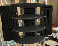
I'll be doing something similar (OB CBT line array with AMT tweeters) using electronic curvature. The prototype will use off-the-shelf 8-channel SSM3582 amps. The ADAU1467 DSP has enough outputs to support 24 channels, each with custom delay and volume. So, the curvature (delay) and shading are all done in software. The prototype amp board is shown in the picture, and the elements to implement the shading and curvature are shown in the SigmStudio snippet. This is an update to the CBT line array described here. I've got all the amps and volume controls working, so I know this amp board will do the job. There will be two of these 24-channel amps--one in each line array.
I realize your approach is quite different, but I'm just suggesting electronic curvature as something you might not have considered. It gets expensive with all of those amps and the wiring is messy, but the software control of curvature and shading is lots of fun to play with.


I realize your approach is quite different, but I'm just suggesting electronic curvature as something you might not have considered. It gets expensive with all of those amps and the wiring is messy, but the software control of curvature and shading is lots of fun to play with.
if you make a long foil i would not orientate the magnets along the length.. since you cant make multiple coils to add the shading. unless you do it by the magnetic field itself.. witch hurts efficiency. or you need to make 30 panels... but then you end up with a worse ctc. never a free lunch  magnet horizontal would make it possible to add as many coils as you like. but then lining them up might be a complete hell.. damned so much troubles always
magnet horizontal would make it possible to add as many coils as you like. but then lining them up might be a complete hell.. damned so much troubles alwaysCool!
The problem for me isn't the physical curve though. If anything I like it since I think it looks really nice!
The problem is that I can't get a single off the shelf driver (or drivers) that does the following:
The closest planar solution I've found is to use a line of PT6825 + a sideways mounted line of PT2522. I tested with one PT6825 on each side to try to drive it as a coaxial but that just made everything worse.
But even in that solution I'd have to add a crossover in in the 1000 - 1400 khz range and I really don't want that if I can avoid it. It also has higher vertical CTC than I'd like which would case lobing. Also, I would prefer the horizontal dispersion of an expensive 3 way to be better than a full range SB65 CBT, not just "not worse". And since the crossover is so high I would get horizontal lobing since I can't put the drivers closer without making it a worse dipole so I'd have to just accept that which leaves a sour taste in my mouth, especially considering how expensive the drivers would be.
The problem for me isn't the physical curve though. If anything I like it since I think it looks really nice!
The problem is that I can't get a single off the shelf driver (or drivers) that does the following:
- Usable range 400 hz - 20 khz with good dipole dispersion.
- High end as good as a planar or a dome.
- Small enough CTC distance between drivers to avoid lobing. Ideally as small as 2 cm.
- Good enough horizontal dispersion, not worse than the SB65.
The closest planar solution I've found is to use a line of PT6825 + a sideways mounted line of PT2522. I tested with one PT6825 on each side to try to drive it as a coaxial but that just made everything worse.
But even in that solution I'd have to add a crossover in in the 1000 - 1400 khz range and I really don't want that if I can avoid it. It also has higher vertical CTC than I'd like which would case lobing. Also, I would prefer the horizontal dispersion of an expensive 3 way to be better than a full range SB65 CBT, not just "not worse". And since the crossover is so high I would get horizontal lobing since I can't put the drivers closer without making it a worse dipole so I'd have to just accept that which leaves a sour taste in my mouth, especially considering how expensive the drivers would be.
Attachments
if you make a long foil i would not orientate the magnets along the length.. since you cant make multiple coils to add the shading. unless you do it by the magnetic field itself.. witch hurts efficiency. or you need to make 30 panels... but then you end up with a worse ctc. never a free lunch
Why can't I make a long foil with the magnets along the length with shading. Wouldn't the early-way-back I suggested in the previous post work? That is as long as I do something to ensure that the coils carry the same amount of current and thus apply the desired amount of force.
Or I guess I could split the long coil into multiple smaller coils. Like multiple drivers but on the same membrane. Probably not as good as a single coil but probably better than completely separate drivers.
Last edited:
The ADAU1452/1466/etc all have 48 channels, but only 4 output ports. You can use TDM to get all the channels in or out, but with I2S you are limited to 4 inputs and 4 outputs. The ADAU1467 has some extra pins to give you 8 more ports, which allows 12 I2S outputs. Each I2S is stereo, so that's 24 outputs.OOh is the ADAU1467 a new version of the 4 way ? thats interesting. i only knew the version with a few channels.. not 24 haha
if you make a long foil i would not orientate the magnets along the length.. since you cant make multiple coils to add the shading. unless you do it by the magnetic field itself.. witch hurts efficiency. or you need to make 30 panels... but then you end up with a worse ctc. never a free lunch
Why can't I make a long foil with the magnets along the length with shading. Wouldn't the early-way-back I suggested in the previous post work? That is as long as I do something to ensure that the coils carry the same amount of current and thus apply the desired amount of force.
...
I think I realized one of the problems with coils along the length, it would probably be difficult to fit enough coils on the foil without it being guaranteed to rip when cutting and gluing.
Adjusting magnet strength would work though. Yes it would hurt efficiency but it won't affect max SPL since that is limited by maximum of the unshaded parts on the bottom. Totalt loss over the whole driver would only be ~ 1.5 dB which isn't too bad. It will probably be plenty efficient anyway
Also, if I have 2-3 traces I could combine the method of terminating the coil partly along the length & adjusting the magnet strength. Then I could probably reduce the efficiency loss to less than a dB which would be even less significant.
And when talking about foils @WrineX... you don't happen to know a good supplier of 12 micron mylar film here in the EU?
ebay here : https://www.ebay.com/itm/325643864449?epid=666550352&itmmeta=01HQ3FV3KT7YV9FFW6DKNSG0S3&hash=item4bd1e30981:g:XBoAAOSwU9xUQPIj&itmprp=enc:AQAIAAAA4OPM/6NBdUkeTndbbfAwsKJYsQ+uT01ty30NELay0ZweSLL4EhVeHm61jgoIG8bbWpnUQEc6XWgW1fJadvyWXidptUdy4XuMA6TmnDyeVI8ppVKKkVlXcl3D6mi6VwUZb7Psushfcp3ecWvNVjy+3RtbxE14yF0VNoX/Ze/+zhXOZyeEv2tNG+FdNKwuOoX5won6D9+iZpTez3cHTiXlO9Ho17mfaadcJr99trlZQGcJI5sznYzNAO9RW4UFKbq4GNRVWfyzt56CVCSwg0P7gjeOkRhQdpRxrT8xXArbfL4Y|tkp:Bk9SR_i57O-4YwAnd when talking about foils @WrineX... you don't happen to know a good supplier of 12 micron mylar film here in the EU?
i buy at ukinsulations.co.uk... but they only sell to companies, i believe
and with shipping an order is 100-150 +euro i just reordered my 12 micron film 200 meter 100 meter 28 micron to test. including shipping 165 euro. why there foil is interesting is there width of 1 meter. ideal for doing 2 larger panels in one go. its actually HOSTAPHAN , not the Mylar branded oneAnd when thinking some more I think adjusting the magnet strength is a bit fiddly. Would make it unneccesarily complicated since the magnets aren't available on the cheap in arbitrary sizes.
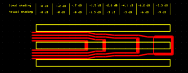
But if I have 3 rows of magnets and 4 coils then I think the following should work:
Id short short the coils to get down to -6 dB without loosing any efficiency. To get to -9 dB I should be able to add an extra shorting trace with such a width such that the paths carry exactly half the current. And if I need to get -12 dB I should be able to repeat it again. I'd only loose efficiency when padding from -6 to -9 and beyond so the practical efficiency loss in watts should be negligable.
Attachments
I couldn't resist and thus I have bought myself a plotter cutter (silhouette cameo 4). So I guess my Flex PCB plans are officialy dead 
So now I just need to buy some mylar + alu foil.
I'm also considering buying some 12 micron kapton tape to compare against the mylar + the extra heat resistance would be nice just in case. But I guess I could achieve comparable results on mylar by just adding a slow blow fuse to the speaker.
(silhouette cameo 4). So I guess my Flex PCB plans are officialy dead So now I just need to buy some mylar + alu foil.
I'm also considering buying some 12 micron kapton tape to compare against the mylar + the extra heat resistance would be nice just in case. But I guess I could achieve comparable results on mylar by just adding a slow blow fuse to the speaker.
Maybe like this as one long membrane with a clever structure traces...
Possibly. A negative of such a setup would be that in practice I believe it would radiate like lots of individual tweeters because of the gap and that the membrane isn't free floating in between the magnet clusters. Won't it basically measure as such with flaws such as long CTC causing lobing but without the ease of manifacturing of going multiple drivers?
Also, since I've completely abandoned pretty much all the initial ideas and requirements of this thread apart from building a planar I think it would be good idea to spin off the new design into a new thread. Hence I have created one!
i would not go thinner, about alu , if you want to reach high over a long tweeter aim for as light as possible. kitchen foil scores already decently good at 12 micron (cheapest roll you can find) but i also used some 7 micron often, you could go thinner mylar to, except undrivven areas becomes a bigger problem so the entire membrane needs to have some alu on it, driven or not, to hold corrugation and prevent it from resonating in the serveral Khz rangeThanks!
Would you recommend using 12 micron for 400 hz - 20 khz or is thicker preferable?
And on the topic of thickness, should I aim for 30 micron as you mentioned earlier or thinner?
thinner foil on thick mylar becomes more and more a trouble holding corugation
thats why 12 micron is rather allrounder for tweeter and i use 30 micron alu for everything else, holds shape better and easy to work with since it already has adhesive@WrineX
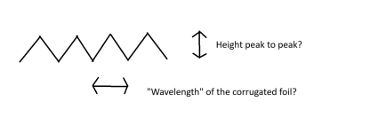
A followup question about your current corrugator + 12 micron mylar and 30 micron aluminum foil:
Have you measured the peak to peak height of a corrugated membrane? And have you measured the wavelength of the corrugation? I'm looking at drawing up plans for my own but I'm not sure what dimensions I should go for. If I should aim for 2 mm peak to peak height or if that is too much and I should aim for less, say 1 mm.
Attachments
I know there is some research done about corrugation height , i never bothered to be fair, since i never had the option to chose whatever i wanted. so it was more of a whatever i can get tool.. also i do not think the differences are that insane (i believe there is a pieces about it in the voice coil magazine/website on a patent about this). i do notice just out of practical reasons tweeters would benefit from small corrugations, making them less heavy and be able to be closer to the magnets while still have some stiffness. also in the top end flat would perform better according to the Ribbon loudspeaker book. but rather unpractical in longer ribbons.A followup question about your current corrugator + 12 micron mylar and 30 micron aluminum foil:
Have you measured the peak to peak height of a corrugated membrane? And have you measured the wavelength of the corrugation? I'm looking at drawing up plans for my own but I'm not sure what dimensions I should go for. If I should aim for 2 mm peak to peak height or if that is too much and I should aim for less, say 1 mm.
Exactly.It will stretch as you will have some tension, if not by the weight itself if a long membrane. And the weight will be higher at top so uneven heights along the membrane...
Since my driver will be so tall (160 cm) I believe I'll need to not just rely on the aluminum itself to keep the corrugations. My current plan is to print toothed TPU gaskets which then locks the corrugations in place.
In the easy case where I have lengthwise magnets I think it should be simple as long as the corrugations are consistent, to handle shift errors I can just make the membrane a few mm longer and allow it to shift up or down to slot into the teeth.
But if I orient the magnets sideways I just realized I would be able to have pretty big corrugations without impacting xmax. That is, if I could ensure that the corrugations only protrude in the area not covered by the magnets. Big corrugations would also make it a lot easier to ensure alignment since printing too small teeth in the TPU gaskets would be a problem.
I think it would be doable but it would probably require me to get creative when corrugating the foil. A normal roller would probably accumulate errors but say if I did a jig that creates a single corrugation and then do them all by eye manually. I could add extra guide lines on the outside of the membrane to help align everything. As long as my error is say within half a mm and independent on all the other existing corrugations then I think it would be feasible.
Attachments
Last edited:
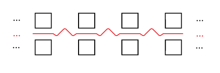
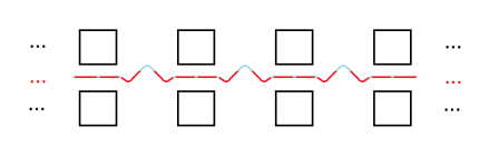
Although a potential problem with the sideways corrugated setup would be floppyness. With the normal config where the magnets are along the length and the corrugations are along the side: the whole corrugations are along the aluminum traces without gaps which should help stiffen everything up.
With the sideways mounted there will be gaps where there is only mylar. Sure I will have aluminum on the sides to help stiffen but at least 70% of the membrane will contain the gaps where the only material is 12 um of mylar which should be a lot more floppy than aluminum.
I did a rough image where the light blue parts are the mylar and the red represents the aluminum traces.
Attachments
- Home
- Loudspeakers
- Planars & Exotics
- DIY midtweeter planar with flexible PCB membrane, a recipe for disaster?