You loose the frequency range (at bottom) because the resonance frequency is shifted to higher. The efficiency is still the same (within the linear range), but the range is narrower.hopefully still soft enough to allow +- 0.5 mm of xmax without too much loss in efficiency.
You loose the frequency range (at bottom) because the resonance frequency is shifted to higher. The efficiency is still the same (within the linear range), but the range is narrower.
Well that might be a problem. Unless it would be well behaved if driven below the resonance frequency.
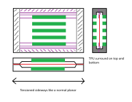
Another crazy idea: what it I did a hybrid solution? Normal planar tensioning in the long axis to make the resonance frequency low but a surround on the short axis? Although it is more complicated so if it would work to just not connect the foild on the top and bottom and leave it flapping while filling the area with some foam to dampen noise might be a more simple and easily reproducable solution.
Attachments
Last edited:
yeah using a suroound i thought about it a few times but since the mylar is not rigid... i asume it still moves like a drumm. the surround might terminate some troubles who knows ") you can use different tensions in X and Y, sideways dictated resonance since its the smallest distance. but getting it to low. might hurt distortion (foil ratling etc)
you can use different tensions in X and Y, sideways dictated resonance since its the smallest distance. but getting it to low. might hurt distortion (foil ratling etc)
you can use different tensions in X and Y, sideways dictated resonance since its the smallest distance. but getting it to low. might hurt distortion (foil ratling etc)look at the carver style. they use corrugation to make it sort of more rigid then use no strech sideways.. really low resonance. but it remains to be seen how wel it does really low... i think i posted a tweeter that uses this idea somewhere. its also in the discussion from Solhaga !
I guess there is no free lunch
You mean like you did in this thread? https://www.diyaudio.com/community/threads/carver-stratec-b-g-rd-and-some-personal-sauce.397812/
As long as the flexible PCB can be corrugated that might work. Your experience that the flex PCBs didn't corrugate as well as your mylar + alu ones might be a problem though. My guess is that it is mainly the metal in the membrane that responds to corrugation. If we roughly calculate the thickness of metal vs not metal by percent then your mylar + alu membranes have ~ 75% where the flex PCB is ~ 11% single sided and 22% with dual sided. Although for all I know copper might hold it's shape better than alu given the same thickness so dual layer copper might corrugate decently enough.
So if I understand correctly:
the resonance frequency of the planar roughly corresponds to the width of the shortest axis that is tensioned? So a Neo8 clone would have the resonance based on the shorter width rather than the height. And this is where the corrugating trick comes in because then the shorter sides are not tensioned so now the longer height determines the resonance frequency?
But since the flex pcb doesn't corrugate that well I'd be afraid that it would loose the corrugation. I guess I could have a flat membrane but I guess I'd have to tension it. And have a big enough driver to bring down the resonance.
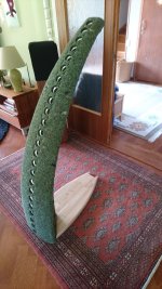
I wonder how well a 20 cm tall 7 cm wide curved driver would work with a flat membrane tensioned mainly along the sides. It would probably have less xmax than if it was flat but it might still work to get +- 0.25 mm xmax. And if it would in all other respects performe awsome I could reduce that to +- 0.1 mm xmax without it being a failure. If push comes to shove I'll gladly bump the low end crossover to 500 hz as long as it can run good enough full range above that.
the resonance frequency of the planar roughly corresponds to the width of the shortest axis that is tensioned? So a Neo8 clone would have the resonance based on the shorter width rather than the height. And this is where the corrugating trick comes in because then the shorter sides are not tensioned so now the longer height determines the resonance frequency?
But since the flex pcb doesn't corrugate that well I'd be afraid that it would loose the corrugation. I guess I could have a flat membrane but I guess I'd have to tension it. And have a big enough driver to bring down the resonance.
I wonder how well a 20 cm tall 7 cm wide curved driver would work with a flat membrane tensioned mainly along the sides. It would probably have less xmax than if it was flat but it might still work to get +- 0.25 mm xmax. And if it would in all other respects performe awsome I could reduce that to +- 0.1 mm xmax without it being a failure. If push comes to shove I'll gladly bump the low end crossover to 500 hz as long as it can run good enough full range above that.
how low do you want tyo play ? since around 8 cm wide would result in around 300-350 hz regular streched at all directions
i would not shoot for less then 1 mm xmax. it becomes really hard to make (slight fuckup and it will hit the mangets non stop, mostly on resonance), an usually is only used for tweeter duty above 2khz like the neo 3 . all others neo 8 and 10 have above 1-1.8 mm , the SOlosound ESL used 8x13 cm but used 4 panels... and where crossed at 350-400. keep in mind that in a esl the bias voltage lowers the resonance some.. then again the foil is 5 times lighter
i would not shoot for less then 1 mm xmax. it becomes really hard to make (slight fuckup and it will hit the mangets non stop, mostly on resonance), an usually is only used for tweeter duty above 2khz like the neo 3 . all others neo 8 and 10 have above 1-1.8 mm , the SOlosound ESL used 8x13 cm but used 4 panels... and where crossed at 350-400. keep in mind that in a esl the bias voltage lowers the resonance some.. then again the foil is 5 times lighter
400-500 hz crossover @ 24 dB / oct is what I am aiming at. If I absolutely have to I can push it higher but 800 hz is the pain limit. Note that I'm of course using multiple drivers in an array which would be 150 cm long although it is shaded so multiply that by ~ 0.7 which rougly translates to an equivalent length of a 100 cm long line.
When you say 8 cm wide do you mean 8 cm wide membrane excluding the frame? One of the requirements (and the main reason I'm looking at planars) is that I need it to be a good dipole with good enough horizontal off axis dispersion to be not worse than a sideways mounted GRS PT2522. That means a total width of max 9 cm and an inner radiating length of 5 cm.
Less width would of course be better since it would be a better tweeter but if I have to choose between "off axis as good as a normal dome but crossover in 800 - 1000 hz" and "off axis comparable to a 2.5" full range (SB65) but crossover in the 400-500 hz range" I'd go with the lower crossover.
Experimental maybe, beware!
A possible way to get have a wider planar but still have a good dipole response without a dipole peak is to wire the traces on the membrane like a coaxial. Say we have 9 magnets and 8 rows of traces with turns but instead of wiring them all in series we wire 2 outer rows, then 4 inner rows and 2 outer rows again. This would allow us to, in theory, say short the outer 4 rows with a highpass crossover and thus halving the radiating width above the crossover improving the performance as a tweeter.
It would make everything more complicated though so if I don't have to I'd rather not. Or at least not until I have a driver I am satisfied with but am looking at ways to improve
Last edited:
Yes i meant membrane width stretched.When you say 8 cm wide do you mean 8 cm wide membrane excluding the frame? One of the requirements (and the main reason I'm looking at planars) is that I need it to be a good dipole with good enough horizontal off axis dispersion to be not worse than a sideways mounted GRS PT2522. That means a total width of max 9 cm and an inner radiating length of 5 cm.
yes you could use 2 coils, and put them in paralel, and filter one to to play up to a frequency while the other does everything , a bit like segmentation in an ESL, when using 3 this gets more complicates (like mid , fullrange , mid) you can.. but you might need to adjust the coils on the mids in impedance to get something usefull
using the carver style is your best bet i think. the small panels in my latest video has a res of 280.. hz while the emiting width is 3-3.5 cm or something.
for these contraptions i was thinking for a long time to segment them if i can, to make the disperion better and they play up to 18Khz or higher . adding length only adds lows. so lower distortion down low. and more output down low.
by the way kapton circuit flex, will not give the same result. you might end up with waay to little top end, the longer they get the lighter you want them to not only boost the lowest frequencies. so you shoot for a to much top end in a small panel, then when you make them larger it will level out. i believe neodymium already mentioned something like this you can ofcourse filter away the low end and you end up with better ditortion but limited efficiency. these where around 85-86dB single ended. to match the bass at this moment ... im -12dB haha i like my panels inefficient
for these contraptions i was thinking for a long time to segment them if i can, to make the disperion better
and they play up to 18Khz or higher . adding length only adds lows. so lower distortion down low. and more output down low.by the way kapton circuit flex, will not give the same result. you might end up with waay to little top end, the longer they get the lighter you want them to not only boost the lowest frequencies. so you shoot for a to much top end in a small panel, then when you make them larger it will level out. i believe neodymium already mentioned something like this you can ofcourse filter away the low end and you end up with better ditortion but limited efficiency. these where around 85-86dB single ended. to match the bass at this moment ... im -12dB haha i like my panels inefficient
Last edited:
I'd drive them fully active so adjusting the respose on the top or bottom is not a problem as long as the drivers perform well and don't have too much distortion.
But with the carver setup, will the kapton + copper flex PCB hold the corrugations? Or would I need to print negative gaskets of the corrugated foil in TPU? I'd have to calculate the depth of the grooves and distance close enought though to it would be a bit more complicated. And I'm not sure if such a setup would increase the resonance frequency since it isn't floating anymore.

But then it might be easier to just have a corrugate shaped TPU surround that is glued to the foil which is then connected to the sides.
But with the carver setup, will the kapton + copper flex PCB hold the corrugations? Or would I need to print negative gaskets of the corrugated foil in TPU? I'd have to calculate the depth of the grooves and distance close enought though to it would be a bit more complicated. And I'm not sure if such a setup would increase the resonance frequency since it isn't floating anymore.
But then it might be easier to just have a corrugate shaped TPU surround that is glued to the foil which is then connected to the sides.
hmm i really dont know, how well it holds. i did corrugate the second one, but it works only if you manage to order without solder mask, or they add 2 extra layers i believe. adding a tpu gaskets etc, might get waay to complicated i think. you can also use the 3d printer to plot a simple alu foil just add a blade holder and off you go. or with a cheap laser setup and add a blade holder instead of a laser.
just add a blade holder and off you go. or with a cheap laser setup and add a blade holder instead of a laser.Yup, I assumed I'd need to ensure without solder mask. I think the best option should be the JLCPCB single side since then the rear would also be without glue and coverlay layer which amounts to 15+15 um.
Complexity is not necessarily a problem as long as I can model the parts, then produce them with high accuracy and in large numbers on my printer. The toothed gasket is more complicated yes but if I can print 100 of them with excellent tolerances so every part fits just right then it might be preferable to manually cutting a foam gasket.
My 3d printer is a BambuLab X1C so it's not moddable in the same way as some others.
But yeah, your blade cutting method seems to work magic. Modifying a laser setup sounds like a lot of tinkering to make it work. Wouldn't a vinyl cutter work just as well or maybe better? Seems to work for this guy. And the ones taking a roll don't seem to be crazy expensive either.
I'm not denying it wouldn't be pretty cool to ditch the multiple drivers and just a do a single 160 cm long curved corrugated aluminum foil based planar. I'd just have to figure out a good way to incorporate the shading network into traces. One way would probably be have enough traces but not have all the traces to go all the way along the planar like this: the yellow parts are the magnets.

Complexity is not necessarily a problem as long as I can model the parts, then produce them with high accuracy and in large numbers on my printer. The toothed gasket is more complicated yes but if I can print 100 of them with excellent tolerances so every part fits just right then it might be preferable to manually cutting a foam gasket.
My 3d printer is a BambuLab X1C so it's not moddable in the same way as some others.
But yeah, your blade cutting method seems to work magic. Modifying a laser setup sounds like a lot of tinkering to make it work. Wouldn't a vinyl cutter work just as well or maybe better? Seems to work for this guy. And the ones taking a roll don't seem to be crazy expensive either.
I'm not denying it wouldn't be pretty cool to ditch the multiple drivers and just a do a single 160 cm long curved corrugated aluminum foil based planar
. I'd just have to figure out a good way to incorporate the shading network into traces. One way would probably be have enough traces but not have all the traces to go all the way along the planar like this: the yellow parts are the magnets.
Last edited:
curved corugated ? i did not know you wanted to curve (somehow did not put 1 and 1 together although you had a cbt speaker i believe) so in the end your goal is a CBT planar ?
i made a cbt ribbon once with shading but very inefficient.
now if thats what you want rotate the coils and magnets and you got whatever amount of drivers on one foil and you can shade them, alias attenuate. ooor use the magnet structure to do so and have a continues foil, like i did with the ribbons.
i gues you seen the series. there are multiple parts. jesus i looked so different only a year ago.. weird
i made a cbt ribbon once
with shading but very inefficient.now if thats what you want rotate the coils and magnets and you got whatever amount of drivers on one foil and you can shade them, alias attenuate. ooor use the magnet structure to do so and have a continues foil, like i did with the ribbons.
i gues you seen the series. there are multiple parts. jesus i looked so different only a year ago.. weird
Last edited:
Exactly, I want to make a dipole CBT planar.
Basically this but as a planar + with a line of woofers is N-frames behind the planar to take care of the low end. Although the wool carpet baffle which helps low end efficiency below 300 hz wouldn't be needed for the planar.
EDIT:
If I did the route traces back-trick, wouln't the efficiency be able to be increased to same-ish as without shading if I after having one trace return home made the other traces bigger in turn? Then resistance would go down so less losses but the current would stay the same so the same SPL?
Attachments
Last edited:
yeah i would think to have as much control after you made them (shading) do the magnets horizontal and create x amount of coils., with values you can add in series parallel etc. so you got as much control of whatever you received i mean i can just make a new one.. JLC because pricey. if you want to go courgated then, you need to use the wiggle patern for the traces. so corrugation would always nick a trace (hit some alu from one trace or another), and the whole foil remains supported. else there will be floppy places every time the corrugation ends up in between the traces. if you would draw a line half way a trace ther should always be some aluminium to be holding shape. ofcourse you can make all the turns square and much wider where its not driven just prevent losing to much impedance on parts that dont make sound.

i mean i can just make a new one.. JLC because pricey. if you want to go courgated then, you need to use the wiggle patern for the traces. so corrugation would always nick a trace (hit some alu from one trace or another), and the whole foil remains supported. else there will be floppy places every time the corrugation ends up in between the traces. if you would draw a line half way a trace ther should always be some aluminium to be holding shape. ofcourse you can make all the turns square and much wider where its not driven just prevent losing to much impedance on parts that dont make sound.
Last edited:
If making a single long then as you say it might be a better idea to have the magnets oriented along the length. Then the corrugation should hold just as well as in your experiments. Also as you say if corrugated along the length then there is less risk of cutting traces. It's almost like they did it that way for a reason
And the desire to use sideways mounted magnets was just for convenience. If I could, without breaking the bank or spending way too much time make or buy a 160 cm long membrane then I'd gladly redesign pretty much everything I've thought of so far. The magnets would be turned the normal way faster than you can blink
Especially since one of the major limitations with a normal CBT is the ctc distance between the tweeter. Multi driver planars aren't perfect here either since they don't radiate perfectly uniform so in practice there is still a lot of lobing. With a single membrane all those problems would go away and I could have pretty much the perfect CBT.
There is now a non zero risk of me... acquiring a vinyl cutter. I found one costing €223 which isn't that much all things considered.
And the desire to use sideways mounted magnets was just for convenience. If I could, without breaking the bank or spending way too much time make or buy a 160 cm long membrane then I'd gladly redesign pretty much everything I've thought of so far. The magnets would be turned the normal way faster than you can blink
Especially since one of the major limitations with a normal CBT is the ctc distance between the tweeter. Multi driver planars aren't perfect here either since they don't radiate perfectly uniform so in practice there is still a lot of lobing. With a single membrane all those problems would go away and I could have pretty much the perfect CBT.
There is now a non zero risk of me... acquiring a vinyl cutter
. I found one costing €223 which isn't that much all things considered.- Home
- Loudspeakers
- Planars & Exotics
- DIY midtweeter planar with flexible PCB membrane, a recipe for disaster?