Re: WOWEEEEEEEEE.........
I'm glad the 551's worked out.")
theAnonymous1 said:This little amp absolutely ROCKS!! It's insanely loud and sounds excellent.
I'm glad the 551's worked out.
Yes, thanks again for recommending it. I like it so much I'm in the process of making a dual mono DIP version for myself to use at home. Each channel will have separate transformers, rectifiers, etc.
I'm kind of stuck on how I'm going to power my gf's portable now. The 7.4v 400mah batteries I was going to use are sold out and prices from other places are just too high. I need a supply with a profile smaller than two 9v batteries.
Anyone know of a small boost converter circuit that can take 3.7v in and output +-8v-10v or single 16v-20v? Prefferably using an 8 pin SOIC chip.
theAnonymous1 said:Anyone know of a small boost converter circuit that can take 3.7v in and output +-8v-10v or single 16v-20v? Prefferably using an 8 pin SOIC chip.
You can try to copy the one off of my HPDAC. It uses a TPS61040 which should do what you want, though it only has 5 pins. Just be aware that layout is important to keeping it stable, and ferrites and re-regulation are important to keeping it quiet.
http://www.ecp.cc/HPDAC.html
dsavitsk said:
You can try to copy the one off of my HPDAC. It uses a TPS61040 which should do what you want, though it only has 5 pins. Just be aware that layout is important to keeping it stable, and ferrites and re-regulation are important to keeping it quiet.
http://www.ecp.cc/HPDAC.html
Thank you again. The TPS61040 looks like a good candidate.
Is there a way to make a dual supply with it using just one battery? Preferably without having to add a separate rail splitter circuit.
If you use two batteries you can make two boost regulators to get your +/- rails just like you would with two positive linear regulators. Don't forget that with a DC-DC convertor Pout=Pin*efficiency. For a boost regulator that means that since the output voltage will be higher than the input voltage the input current will be higher than the output current. Something to keep in mind since you'll be using batteries.
BWRX said:If you use two batteries you can make two boost regulators to get your +/- rails just like you would with two positive linear regulators. Don't forget that with a DC-DC convertor Pout=Pin*efficiency. For a boost regulator that means that since the output voltage will be higher than the input voltage the input current will be higher than the output current. Something to keep in mind since you'll be using batteries.
Yeah I was thinking about two boost circuits in series but 2 boost circuits + 2 batteries = 2 big.
I realize the current draw from the 3.7v battery will be quite a bit. I have a few 3.7v 800mah lithium cells. She will only ever use it for a couple hours at a time so that should be enough.
Maybe just doing 3.7v to 18v and then using a resistor divider for the rails is the simplest smallest solution. But then there's the issue of the divider resistors eating up current.

theAnonymous1 said:
Yeah I was thinking about two boost circuits in series but 2 boost circuits + 2 batteries = 2 big.
I realize the current draw from the 3.7v battery will be quite a bit. I have a few 3.7v 800mah lithium cells. She will only ever use it for a couple hours at a time so that should be enough.
Maybe just doing 3.7v to 18v and then using a resistor divider for the rails is the simplest smallest solution. But then there's the issue of the divider resistors eating up current.
I have to wonder if it would be simpler to design a very simple power amp that can go close to the rails say 3-4 Vpp off of +/- 3.6V (7.2V total) batteries, than to include boost circuits and so on. A very low power rail to rail OP amp with an output buffer is another possibility.
Wondering if it can be made to sound good with very low idle currents leads to the thinking that it would be interesting to have it turn off the current sources and output stage with the lack of an input signal, and power up at higher idle currents with an input signal. This could have a very long on dwell time so that on/off switching is not an issue from cut to cut.
Just offering the ideas since this thread has me thinking about the problem.
Pete B.
PB2 said:
.I have to wonder if it would be simpler to design a very simple power amp that can go close to the rails say 3-4 Vpp off of +/- 3.6V (7.2V total) batteries, than to include boost circuits and so on. A very low power rail to rail OP amp with an output buffer is another possibility.
.
If you need a
- very low drop of voltage ( like Input Voltage -0.1 Volt worst case )
- extremely low supply current ( around 0.100 mA consumption)
- precision
Discrete Regulator - 3 small transistors
I have such a circuit!
Actually I have one working. set for 5.00 Volt output
*******************************************
More information on FEATURES of my regulator circuit:
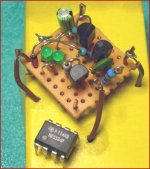
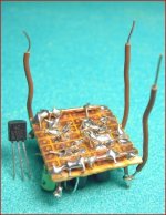
Microphone Amplifier 9 Volt Battery Discrete Regulator
See attached picture of my little great regulator!
As most voltage regulators chips it has 3 pins: in, out, gnd
For size compare I have used an Audio Op-Amp IC in my image
Regards
lineup
Lineup Audio Circuits
Attachments
Ok, it seems like every time I solve one problem it creates another.
I'm going to go a completely different route now I think. I have some TPA6111A2 150mw stereo headphone IC's left over from my first attempt at a portable amp. It worked good, but just lacked some power. I will admit that when I tested the TPA6111A2 with the custom earbuds I hadn't discovered they were 150 ohm yet. I was under the assumption they were 25 ohm, so results should be better with the new phones when they arrive.
http://focus.ti.com/lit/ds/symlink/tpa6111a2.pdf
The idea I have is to use two stereo IC's each in a BTL config. I will then power each circuit with it's own 3.7v lithium battery. By using seperate batteries I can then tie one output from each circuit together so that a standard stereo connector can be used.
Below is a pic of what I have in mind. I'm not sure if this is the correct way to do it, but it seems logical to me.
I got the idea from the similarity with a Tripath amp bridging diagram.
I'm going to go a completely different route now I think. I have some TPA6111A2 150mw stereo headphone IC's left over from my first attempt at a portable amp. It worked good, but just lacked some power. I will admit that when I tested the TPA6111A2 with the custom earbuds I hadn't discovered they were 150 ohm yet. I was under the assumption they were 25 ohm, so results should be better with the new phones when they arrive.
http://focus.ti.com/lit/ds/symlink/tpa6111a2.pdf
The idea I have is to use two stereo IC's each in a BTL config. I will then power each circuit with it's own 3.7v lithium battery. By using seperate batteries I can then tie one output from each circuit together so that a standard stereo connector can be used.
Below is a pic of what I have in mind. I'm not sure if this is the correct way to do it, but it seems logical to me.
An externally hosted image should be here but it was not working when we last tested it.
I got the idea from the similarity with a Tripath amp bridging diagram.
An externally hosted image should be here but it was not working when we last tested it.
I've got nothing to contribute to the thread directly , just posting to applaud your sentiment generally. My (ex) S/O had significant hearing difficulties, yet loved music... Iunderstand where you are coming from.
(funnily enough she loved my (large by UK standards) horns but hated the ESLs - which I sold...)
(funnily enough she loved my (large by UK standards) horns but hated the ESLs - which I sold...)
Any update with the new low impedance headphones?
As far as the bridged configuration you show there, why not try it first unbridged? With Low Z phones you'll need a lot of current.
The requirements for the amp depend on the load impedance, and since some of these OP amps are marginal driving low Z loads it is good to first look at your requirements. How many volts out do you need to the phones? Then calculate the current. I'm sure you know this, but it is good to step back and first determine what you need.
I tried a TLO82 with a transistor output stage, +/- 9V supply and found that the OP amp limited the swing to about 6 Vpp. My mp3 player puts out about .5 Vpp and even just 1-2 Vpp is very loud, bass comes almost as wind out of my Grado phones. Yet it does not seem to sound so good, don't know, perhaps it is too much for the phones, or some filtering is required. I should probably try a better front end, as it just sounds a bit rough and grainy. I have found that it has a tendency to oscillate, then it sounds real bad. I just wired it on a proto board so that is probably part of the problem.
I'm very tempted to do a simple discrete design but I don't really need a headphone amp. Also, rail to rail video OP amps look good, on paper anyway, since they're designed to drive 75 ohm loads. 3 in a package are available (AD813 http://www.analog.com/en/prod/0,2877,AD813,00.html ) and they could be paralleled for even lower impedance loads.
Are you planning to fit it into an Altoids case?
Hi PB2,
I'm still waiting for the new phones to show up. I don't know whats taking so long. I will have to call and check up on their status Monday.
I've already built the bridged circuit I proposed above. The output power seems on par, if not a bit better than the OPA551 board @ +-9v. The OPA551 board sounds better in my opinion, but sound quality isn't the most important thing here.
http://i16.tinypic.com/33af5ug.jpg
I think I will end up using the OPA551 board though. I found some lithium cells the size of AAA batteries. Four of these in series should work out well and still be relatively small.
http://www.batteryspace.com/index.asp?PageAction=VIEWPROD&ProdID=2598
I'm trying to aim for something a bit smaller than an altoids container.
PB2 said:I forgot to mention, you can't bridge since there is a common lead for right and left?
True, but I found a way around this problem by accident. I tied one output from from each chip together to great the common "ground" for the headphones. Then, instead of referencing the input signal to the normal input ground(battery -), I referenced it to the new common ground on the outputs.
I know, crazy, but it worked.

theAnonymous1 said:
True, but I found a way around this problem by accident. I tied one output from from each chip together to great the common "ground" for the headphones. Then, instead of referencing the input signal to the normal input ground(battery -), I referenced it to the new common ground on the outputs.
I know, crazy, but it worked.
Hi, well it's interesting how things technically incorrect can sort of work. If it works at all it is because most source material has much common mono content. The common bridged signal is now mono. If you drive one side only the common connection will have the two amplifiers fighting. There will be very high cross currents if you've wired it as I think you have.
Pete B.
PB2 said:I tried a TLO82 with a transistor output stage, +/- 9V supply and found that the OP amp limited the swing to about 6 Vpp. My mp3 player puts out about .5 Vpp and even just 1-2 Vpp is very loud, bass comes almost as wind out of my Grado phones. Yet it does not seem to sound so good, don't know, perhaps it is too much for the phones, or some filtering is required. I should probably try a better front end, as it just sounds a bit rough and grainy. I have found that it has a tendency to oscillate, then it sounds real bad. I just wired it on a proto board so that is probably part of the problem.
The problem was probably a combination of poor connections (old proto board) and the compensation cap being off by a factor of 10. There was not enough major loop gain to cover the output stage, the frequency response was not even flat. It's all fixed and sounds very good, a lot of headroom! Still it is not optimal since it cannot even come close to the rails which would allow lower voltage batteries to be used. This is easy to fix with a rail to rail OP amp.
OK folks, any favorite rail-to-rail OP amps that are low power, will run on say +/- 3 V, and sound good? Output current drive is not important as I'm using transistor buffers. AD822? or MAX4494?
Pete B.
- Status
- This old topic is closed. If you want to reopen this topic, contact a moderator using the "Report Post" button.
- Home
- Amplifiers
- Headphone Systems
- DIY headphone amp not loud enough