theAnonymous1 said:I finished drawing up the board for the OPA551. I have to connect two nets with jumper wire, but I think it came out pretty good considering it's single sided with the components so close together. Size is approximately 25mm x 25mm.
Looks pretty nice. I think if you futz with it a lot you can eliminate those jumpers, but it is probably not worth the time. Jumpers should be fine.
As for the 45 degree thing, this only really matters for super high frequencies. You should be fine here.
theAnonymous1 said:I think I'm also going to order an AD8397. It will fit on the board I already made and has pretty high output current.
Be forwarned that this chip is a beast to work with. Without a lot of attention to a lot of details (decoupling, ferrites on the output, caps in the feedback loop, etc.), it will oscillate and destroy itself, and perhaps your headphones. Even when not oscillating, it is prone to a lot of offset. Look at Headwize for discussions of the Mini3 and the Pint, and good luck. People do seem to like it when they get it to function. I still think the LM6172 sounds a little better, but a lot of people disagree. Oh, and the NJR4556 is another high current opamp to try. It is used in the Grado RA-1, and only costs like $0.50 so is worth the experiment. All of these are prone to oscillation and offset, but the SAD8397 is the worst of the bunch.


dsavitsk said:As for the 45 degree thing, this only really matters for super high frequencies. You should be fine here.
A layout that works well at high frequencies will also work well at low frequencies, but not vice versa.
Here is a pic with the silk layer so you can better see what everything is......
An externally hosted image should be here but it was not working when we last tested it.
Anonymous1, I whipped up a quick schematic in Eagle and routed a board as well. There is no easy way to do a one sided layout without jumpers when two separate chips share supply rails. I liked your idea of a solid ground plane on the back and ran with that. For this layout you'd have to drill out the 4 ground pads and solder your wires on both sides to connect them to the ground plane. You'd also have to jumper each supply rail over to the chip on the right.
Attachments
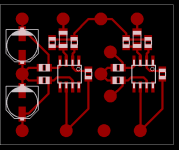
Feel free to use it if you'd like. The main change I made was to add supply rail decoupling caps for each chip. It is best to place them as close to the chip's power pins as possible.
I can send anyone the eagle schematic and board files if they want to play around.
The actual dimensions of the board outline are 1.375in by 1.1125in.
I can send anyone the eagle schematic and board files if they want to play around.
The actual dimensions of the board outline are 1.375in by 1.1125in.
Attachments
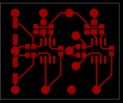
Here's an example of a headphone board I've built, probably way overbuilt with bypass capacitors. It's about 1.4 x 2.3 inches, but could be made alot smaller by eliminating caps. It's single sided with one short jumper.
An externally hosted image should be here but it was not working when we last tested it.
Fenris, thank you for the offer. I am in the middle of etching my board and would like to try and see how the OPA551/2 work out first.
Brian, thanks for making up that board. If the one I'm etching now doesn't turn out maybe I'll give it a try.
Doing double sided toner transfer is pure hell. I had to redo it 4 times already using acetone to clean the toner off.
I'll post a pic of the board when it's done as long as it's not too horrible looking. It's taking forever to etch double sided 2oz. with spent ferric chloride.
often there is much less traces on one side... drill the holes and manualy draw one side with a marker.... I do it all the time
I leave my FeCl in an open bowl... most of the water evaporates... when I need it I just pour some boiling water in and stir the crud up.. the heat helps much.
Get those decoupling caps even closer if you can..
I leave my FeCl in an open bowl... most of the water evaporates... when I need it I just pour some boiling water in and stir the crud up.. the heat helps much.
Get those decoupling caps even closer if you can..
Nordic said:often there is much less traces on one side... drill the holes and manualy draw one side with a marker.... I do it all the time
I leave my FeCl in an open bowl... most of the water evaporates... when I need it I just pour some boiling water in and stir the crud up.. the heat helps much.
Not a bad idea Nordic. Drawing some line with a sharpie would have been a lot easier.
Board is done. Now I just have to wait for the FedEx guy to show up tomorrow.
")
Wish I has some tin plating solution.
Top.....
An externally hosted image should be here but it was not working when we last tested it.
Bottom....
An externally hosted image should be here but it was not working when we last tested it.
Thanks Brian. Now I just have to find where I put my tiny drill bit.
I have another question about this project. I plan on using two 7.4v lithium batteries with a real ground point. I noticed that when doing it this way you have to disconnect both + and - at the same time or you get huge DC offset.
The pot I plan on using has a built in switch, but it's only a single pole. How can I disconnect both the + and - supply leads with a single switch? I know the obvious answer would be a relay, but they are too current hungry for a portable amp. Is there any other way?
Nice job on the board. I use HCl and H2O2 to etch (and toner transfer) - I think it's easier than FeCl. Also, to tin I've stopped using Tinnit, it was more trouble than it was worth. I now just wipe a very thin layer of flux on and then use my iron to cover the traces with solder. It's actually faster than Tinnit (unless doing several square feet at a time). I don't think there's a way to switch on the amp with only a SPST switch without using a relay. A small 12v relay will have about 1500 ohm resistance. Use a 350 ohm resistor in series and use both batteries to switch it on/off. Current draw should be about 8ma. If you're already having problems sourcing 40ma of current from each opamp and expect to probably be drawing 100+ma from each, 8ma is negligable. Plus it will draw equally from each battery, so they won't drain unevenly.

Fenris said:I now just wipe a very thin layer of flux on and then use my iron to cover the traces with solder. It's actually faster than Tinnit
I totaly do the same...
If you don't own flux, go and buy some before you solder another dot. You get nice big jars of it at the hardware shop, plumbers use a tone of the stuff to solder pipes..
WOWEEEEEEEEE.........
I just finished the board, and it works. I soldered all the resistors and caps while I was waiting for FedEx to deliver the OPA. Right when I was about to unplug my iron I heard they guy put the box at my door. FedEx is awesome.
This little amp absolutely ROCKS!! It's insanely loud and sounds excellent.
It plays loud enough that I could actually blow the earbuds I tested it with if I tried. Any loud bass notes in a song makes my earbuds distort and crackle from over excursion. I have the gain at 11 like the last amp and even with my mp3 players volume all the way up; I don't hear any clipping or distortion from the amp itself. I am very satisfied with how it came out.
I can't test it for it's intended purpose yet because I still have to wait to get the new pair of lower impedance custom buds back.
I would like to thank everyone who help out. I love this place.
An externally hosted image should be here but it was not working when we last tested it.
Operator: good morning this is Fedex, how can I assist you...
Caller: I have a package I need delivered to Idaho...
Operator: Its allready delivered
Caller: No it isn't its right here on the kitchen tabl... hey!!! wait where is it now?
Operator: Your dad is trying on the shirt right now....
Nicely done mate
Here is a picture of my near completed build... still have to attach one screw mount, but it all works and everything.. went for gain of 4.7 eventualy and used some Oscon caps I got from Franz G.
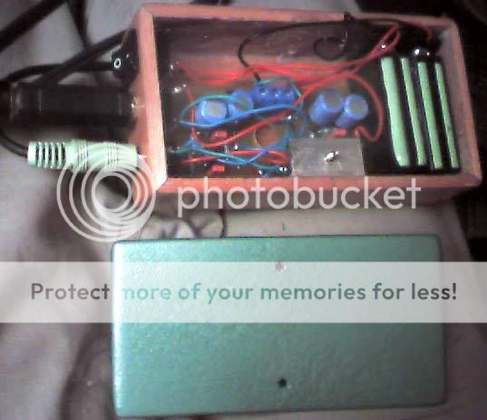
I'm giving it to a friend I had since school for his birthday tommorrow.
Caller: I have a package I need delivered to Idaho...
Operator: Its allready delivered
Caller: No it isn't its right here on the kitchen tabl... hey!!! wait where is it now?
Operator: Your dad is trying on the shirt right now....
Nicely done mate
Here is a picture of my near completed build... still have to attach one screw mount, but it all works and everything.. went for gain of 4.7 eventualy and used some Oscon caps I got from Franz G.
I'm giving it to a friend I had since school for his birthday tommorrow.
Nice work, looks like you've got a good solution.
I would have suggested a simple output buffer like Figure 14
here on Self's page:
http://www.dself.dsl.pipex.com/ampins/webbop/opamp.htm
It should be possible to do this without large caps, and at lower standby current than with the OPA551. A low power OP amp, driving a very low bias AB output stage for example.
CMOY burns power just in producing the split supply, and then
it requires large caps.
You should be able to use series pass BJT or FETs on the +/- supply, and have the power switch just bias both on, rather
than a relay. Or you could just use a double pole switch.
Pete B.
- Status
- This old topic is closed. If you want to reopen this topic, contact a moderator using the "Report Post" button.
- Home
- Amplifiers
- Headphone Systems
- DIY headphone amp not loud enough