Vix said:If I understand correctly, F2 with a 16 ohm lightbulb is going to have around 16 ohm output impedance? (actually slighly less than that, assuming we connect 100 ohm bleeder resistor, as was done in Zens).
Another point it brings is the correct DC value at the drain of mosfet. If the PSU voltage is around 40, then, should it be set at half that value, or actually less (12 to 15v) as was the case with Zen lite? I guess it will work both ways, but which is the "proper" one here?
Yes, 14 ohms or so, with 100 ohms on the output.
You probably want to set the Drain at about 15 volts, and with
2.5A going through the 16 ohms of light bulb, there's 40 V
across that, so you want to see a regulated (or at least filtered)
supply of 40+15 = 55 V.

Hi,
I’m trying to make a workable circuit out of something that remained from a previous project...
To avoid confusion, it went like this: At first I built Zen V3. (and Boz as well) Then, after some time, I modified it and got a SEWA (albeit with a higher supply voltage than the original Sewa). Then, I received my Jfets (thanks Grey). I had enough scrap parts around, so I built Zen V8. Played with it for a while. Then, got a soldering iron, dismantled sewa, …and ZEN V9 was born. On the other hand, I got this wooden box, with a pair of 1500w 220 v halogen lamps on top (ex-V8). It still contains the transformer, caps, supply filter (the same as the one described in Zen v9), heatsink, input and output connectors…mmmm…
Could you just leave it like that, in the corner, taking a glance at it and do nothing? It just begs for a few resistors and…it may become an F2 lite.
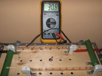
It has around 45V after filtering….so…not exactly there, but close enough. I just need to find some free time….
Will report when it gets done
Vix
I’m trying to make a workable circuit out of something that remained from a previous project...
To avoid confusion, it went like this: At first I built Zen V3. (and Boz as well) Then, after some time, I modified it and got a SEWA (albeit with a higher supply voltage than the original Sewa). Then, I received my Jfets (thanks Grey). I had enough scrap parts around, so I built Zen V8. Played with it for a while. Then, got a soldering iron, dismantled sewa, …and ZEN V9 was born. On the other hand, I got this wooden box, with a pair of 1500w 220 v halogen lamps on top (ex-V8). It still contains the transformer, caps, supply filter (the same as the one described in Zen v9), heatsink, input and output connectors…mmmm…
Could you just leave it like that, in the corner, taking a glance at it and do nothing? It just begs for a few resistors and…it may become an F2 lite.
It has around 45V after filtering….so…not exactly there, but close enough. I just need to find some free time….
Will report when it gets done
Vix


Hi,
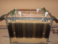
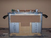
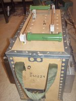
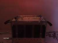
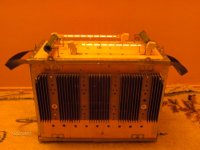
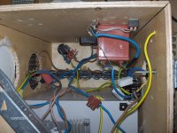
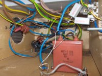
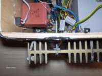
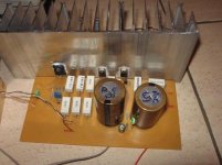
I guess that most of you wanted to see the interior of an F2, so I have made some pics. Nothing fancy, a lot of mess. I used various pieces of wire, not minding the color, as long as I was careful while making connections. Round holes seen on the inside are the result of my previous attempt to use 12v ceiling halogen lamps in series as a current source. While they looked nice from the outside, they released too much heat on the inside of the enclosure..so..I abandoned that approach, removed the reflectors, and put halogen sticks on top. To get a little bit more current, I added 75 Ohm resistors in parallel. The switch on the top serves to connect/disconnect these resistors (although it stays connected most of the time). I've decided to connect 220 ohm bleeder resistor at the output. With 1500w 220v lamps and 75 ohm resistors, F2 lite may have around 12 to 13 ohm output impedance.
Input capacitor is a 10 uF one, just because it was already there from a previous project, and I was too lazy to replace it...
Attachments
Recently I have read Dick Olsher’s review of NoBox open baffle speaker kit from Visaton:
http://www.enjoythemusic.com/magazine/equipment/0606/visation_nobox_bb_loudspeaker.htm
He says that it works exceptionally well with an F2. Since I already have Visaton B200 speakers and some 12 inch woofers, I was contemplating about building something similar to that, and drive it with F2 lite.
However, one thing is confusing here. If you take a look at the crossover, you will notice that it is optimized for voltage amplifiers. And it worked well with an F2? Shouldn’t F2, being a current amp, require a different (series) crossover to achieve the desired effect?
I'd be very thankful if somebody can shed some light on this.
Regards,
Vix
That should be easily understoodMmmm….I don’t want to press the Stop button on my CD player….
Nice job and the glow is really cool, Vix Those inputcaps looks like russian Paper-in-oil caps. Another advantage of your amp is: easily moveable Steen
steenoe said:.............. Those inputcaps looks like russian Paper-in-oil caps. ...........................
Steen
probably from butchered russian spks
steenoe said:That should be easily understood
Steen
Thanks.Yes, these are russian caps.
Zen Mod said:
probably from butchered russian spks
I bought them at a speaker shop in Bulgaria two years ago.
They still seem to have these caps in stock.Line level passive filter looks promising. Or...I have a DIY active 2nd order low pass filter, with adjustable frequency. I could get it to around 200 Hz. That would be for the woofers. For B200, the simplest way would be to create 1st order high-pass, by reducing the value of the input cap?
This would have one caveat, however.
Woofers would not be driven by an F2 (unless I build another copy, which is not likely to happen at this moment). As I could notice from the review, it was the woofer that was benefiting most from a current amp. On the other hand, it is much easier to implement this than deal with those inductors....
Regards,
Vix
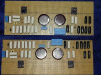
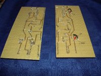
Pic of my F2
I've just completed building F2 to drive my old Flat8A. With typical voltage amp e.g. GC, JLH, Hiraga, blamless etc., it sound fat and muddle. But with F2 without the output resistors, it opens up the top end, pushes the music resolution to a higher degree and make the vocals sweet and nice. Is this the sound of second harmonic? Not according to what I've read so far. Why other single ended class A like JLH does not sounds like that? Can anyone describe the sound of second harmonic to me?
Will add the ouput resistors later on to see how it will change the sound.
Thanks Mr. pass for his generosity to share the design and Babowana for your comments.
Here's the pic of my F2
Attachments
- Home
- Amplifiers
- Pass Labs
- DIY F2 clone