Would this work for a transformer for BOTH channels (i.e., one transformer for the stereo pair)?
Howzabout a pair of these for the heatsinks?
Hopefully, these will works as they're pretty cheap. If so, then the answer to the question, "Who rocks the party that rocks your body" would be, "Kofi rocks the party that rocks your body"
K to the ofi
Howzabout a pair of these for the heatsinks?
Hopefully, these will works as they're pretty cheap. If so, then the answer to the question, "Who rocks the party that rocks your body" would be, "Kofi rocks the party that rocks your body"
K to the ofi
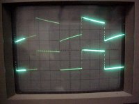
I found out that the F2 is very accurate in producing a square wave without load. I presume that this is the way Nelson did the 10Khz test. Looking at a 400Hz and lower square wave, the distortion rises (see picture of 100Hz 300mV input, upper wave is output).
Ones speakers are connected, one needs to trim the wave with capacitors and resistors as outlined in the paper http://www.firstwatt.com/downloads/cs-amps-speakers.pdf
This seems fairly tricky to me as the ideal combination for say 1Khz is not necessarily optimum for 10Khz. I found it to be a very nice exercise to perform together with extensive listening tests.
/Hugo
Attachments
So, the square wave should be nice all along the audio band?
Hmm...wonder what could cause this. I'm pretty sure I did wire everything correctly. I admit I need some kind of buffer as the amp plays tricks on my el-cheapo audio generator. At 10Khz it looks more like a sawtooth.
/Hugo
Hmm...wonder what could cause this. I'm pretty sure I did wire everything correctly. I admit I need some kind of buffer as the amp plays tricks on my el-cheapo audio generator. At 10Khz it looks more like a sawtooth.
/Hugo
square wave metalfilm resistor resistance inductance capacitance
To my function generator
which has an output optimized for 50 ohm, (can use BNC output)
I most often put a resistor in parallel with input
so the total resulting load the generator see
will be ~ 50 ohm.
---------------------
Lineup comment:
Normal Metal Film small resistors
have almost ideal qualities
only between like 100-470 Ohm!
Below 100 Ohm they can be regarded as inductive
while above 470 Ohm they become more or less capacitive
at higher frequencies, as when square waving.
Square wave is a composite of harmonics. Some with very high freq!
We have all heard of 2nd, third, fourth, the troublesome 7th and 9th and so on ...
Haven't we?")
All components, even wires and resistors, have L, C and R.
We also have heard of different capacitance in semiconductors
as well as transistors have inductive behavior in some instances.
The difference is only how much or little they have of each.
Why we call them wire, resistor, capacitor, inductor
is because they have one dominant of such behavior.
What we call a resistance, can and will act as
mainly one capacitor or inductance at some frequencies.
================================================
Due to this effect,
where very small capacitances, inductances cause in-linearity at extreme frequencies,
I recommend this:
At 10 MHz we should avoid using metal film > 1 MOhm.
At 100 MHz, use <= 10 kOhm metal film resistors.
And here I am talking about those standard 0.25-0.60 Watt metal film resistors
we usually put into audio circuits.
Other types of resistors, will have other L, C, R contents.
================================================
Regards to F2 Clone builders & Testers
lineup One of diyaudio.com MVP (Most Valuable Players)
Lineup Audio Test Lab
PS.
... if you found this a good and valuable post
... please vote it as one 5 ***** stars contribution.
DS.
Nelson Pass said:If you have a high source impedance on the generator, you
will see roll off on the square wave due to input capacitance.
To my function generator
which has an output optimized for 50 ohm, (can use BNC output)
I most often put a resistor in parallel with input
so the total resulting load the generator see
will be ~ 50 ohm.
---------------------
Lineup comment:
Normal Metal Film small resistors
have almost ideal qualities
only between like 100-470 Ohm!
Below 100 Ohm they can be regarded as inductive
while above 470 Ohm they become more or less capacitive
at higher frequencies, as when square waving.
Square wave is a composite of harmonics. Some with very high freq!
We have all heard of 2nd, third, fourth, the troublesome 7th and 9th and so on ...
Haven't we?
All components, even wires and resistors, have L, C and R.
We also have heard of different capacitance in semiconductors
as well as transistors have inductive behavior in some instances.
The difference is only how much or little they have of each.
Why we call them wire, resistor, capacitor, inductor
is because they have one dominant of such behavior.
What we call a resistance, can and will act as
mainly one capacitor or inductance at some frequencies.
================================================
Due to this effect,
where very small capacitances, inductances cause in-linearity at extreme frequencies,
I recommend this:
At 10 MHz we should avoid using metal film > 1 MOhm.
At 100 MHz, use <= 10 kOhm metal film resistors.
And here I am talking about those standard 0.25-0.60 Watt metal film resistors
we usually put into audio circuits.
Other types of resistors, will have other L, C, R contents.
================================================
Regards to F2 Clone builders & Testers
lineup
One of diyaudio.com MVP (Most Valuable Players)Lineup Audio Test Lab
PS.
... if you found this a good and valuable post
... please vote it as one 5 ***** stars contribution.
DS.
Babowana said:What is the function of R1 (1M)?
Zen Mod said:protection;
in case that preceding stage doesn't have same purpose resistor after coupling cap.
Papa must put this there,his amp is (sort of) commercial.
you are not obliged to do the same
Last night, I was watching DVD movie, The Memory of a Killer (Zaak Alzheimer, De)
Thriller . . .
At the first scene, a train was running across the screen at night time.
The train was fast off, leaving a dark house in the middle of the scene.
Camera was zooming up a small pink-light window at the corner of the house slowly . . .
With lightning and thunder behind . . . gloomy . . .
Scary . . .
Yeah!
It’s a lightning arrest. Huh . . . ?
This is a general question regarding the effect of inductance present on wirewound power resistor that could be used as Source resistors such as on this F2 amp (R7-R12).
Of course not all wirewound brands of same value and thermal capacity will have the same inductance.
In short, the questions is of the effect we can expect when using such resistors on these application, be it soundwise and/or general measurement effects.
I can see that Nelson avoids using wirewounds on this position, any reason?
Babowana said:Scary
JH,
you're also working on an F2 for your Fostex locomotives ?
(the next hustles from Brussels movie is called: Hugo does Hollywood. I'm not exactly sure about the genre,but it's supposed to be scary too)
jacco vermeulen said:you're also working on an F2 for your Fostex locomotives ?
Hugo does Hollywood
Hi Jacco,
Afraid no. Not yet. Still digging Zen V5 and burrying myself into it.
Expecting Hugo Does Hollywood . . .
Regards
apassgear said:wirewound power resistor that could be used as Source resistors
Almost all my amps have wirewound Source resistors
I'm happy in using them
So, I don't care the internal L values
Netlist said:I'll try that.
If it helps, I give you 6 stars.
/Hugo
The most important, star or no star,
is that you get your test setup
as good as to show fair values.
Both Nelson Pass original good advice,
as my attempt to go into dept about this mechanism
of resistors behaving in a non linear way,
and give away my knowledge of some aspects of standard metal film resistors,
may be useful for you.
It is a good chance it would help.
But only you will know when trying.
Good Luck
to my old mate (before he became member of dreaded, much feared board moderator gang)
Netlist
from
lineup,
halojoy
etc
etc
you may call me anything you want
i am still only me Lack of time prevents me from doing more tests but yesterday evening I found a few minutes to play with the generator. Long story short, I found out its broken somewhere but managed to tweak a bit here and there and finaly it was up and running more or less as it should.
All in all, with no speaker connected, the F2 is doing fine all along the audio band.
Figures are now much better, square wave remains a square wave.
With speakers attached, I see a bit of overshoot at the top that needs further investigation.
Playing with the R's is next on the list.
/Hugo - Who rejoices the presence of his initial replier in Introduction.
rejoice
thanks man
good to hear, it is alright again with your squares
they are indeed a good tool them square waves
for analysing effects of the final setup trimming of amp
... that bit that is perhaps the most tricky one ...
to try some compromises to get nice and stable output into real loadings
anybody can draw a schematic
even near to a perfect one
not all can get a good working amplifier
out of a good idea in a schematic
lineup
=============================================
Appendix 1. ----- still is keeping surprisingly high validity - compared to actual facts -----
2003-01-18: lineup welcome to a new member: Netlist
hello, netlist
hope you and me can become friends - and stay friends
You will notice that I am a living creature (made by Creation)
I don't undress my personality, just to fit in, in any place.
Take me as I am - or I resign .....
Almost all my amps have wirewound Source resistors
I'm happy in using them
So, I don't care the internal L values
Thanks for the reply Babo
On my amps I also use wirewounds as source resistors but was wondering why others like Nelson avoid using them on this position and though it might be because of inductance and or sonic reasons.
- Home
- Amplifiers
- Pass Labs
- DIY F2 clone