Sanders Sound Systems - electrostatic - Page 4
Roger Sanders explains the 'bass quality' perception in this post?
Roger Sanders explains the 'bass quality' perception in this post?
Hi, it has been a while since my last visit here, but a few weeks ago I made another measurement, in my garden, the esl placed on a table and the microphone positioned at three meters distance from the esl. This time I managed to get a graph that explains my idea of lack of lower range frequencies.
I also painted my esl's white and I'm very pleased with the result, not only esthetically but I enjoy the audio quality as well. Friends of mine seem to enjoy the sound too so the result is better than expected. No technical problems until now.
As I find it very relaxing to be in the process of actually building something, I decided to continue and build another pair of esl's, but much bigger. I had the option to go for a two way hybrid design and supplement the current els's with magnetic woofers but as I prefer simplicity and clean and tight sounding lower frequencies I decided to build bigger esl's. Membrane dimensions will be 50x160 cm (20x63 inch).
Regards, J.
An externally hosted image should be here but it was not working when we last tested it.
An externally hosted image should be here but it was not working when we last tested it.
Recently I finished my first stator of my new project. They measure 52x160 cm (diaphragm). Main reason for choosing those large dimensions was lack of bass in previous smaller model.
It took me a lot of time to build them (second one is almost finished) and I was very happy and a bit surprised when turning up the volume they seemed to play well: no hiss, sparcs etc. Even the amplifier seemed ok.
But during following listening sessions I noticed that although they have much more low frequency range, they sounded rough / smeared, not clean, compared to the small stats. Sometimes they sound a bit boomy.
So I was a bit disappointed after all the hard work. I would like to get a scope and do some measurements but I'm wondering what could be the source of this problem? Could it be the undamped (fundamental) resonance? I measured it at 25 Hz. I didn't place any screen to damp it. Could these resonances also affect higher frequencies? Would sound quality improve by placing an air resistive screen against the rear stator? (I just ordered 72T silk screen damping mesh for testing)
An externally hosted image should be here but it was not working when we last tested it.
Last edited:
A colleague of mine who built his own electrostatic loudspeakers a couple of years ago certainly had the impression that partial resonances coloured the midrange. He then put a blanket behind the loudspeakers to improve this (and to damp the fundamental resonance), but always regretted that he hadn't included a proper acoustic resistor as close to the diaphragm as possible, that is, between the diaphragm and the stators.
By the way, he wrote a very fascinating website about all of it: Elektrostatic Loudspeakers
By the way, he wrote a very fascinating website about all of it: Elektrostatic Loudspeakers

Congratulations! They look quite niceRecently I finished my first stator of my new project.
")
Yes. Damping the diaphragm resonances often improves midrange clarity as well.…Sometimes they sound a bit boomy….Could it be the undamped (fundamental) resonance? I measured it at 25 Hz. I didn't place any screen to damp it. Could these resonances also affect higher frequencies? Would sound quality improve by placing an air resistive screen against the rear stator? (I just ordered 72T silk screen damping mesh for testing)
I would highly recommend it.
Note that the 72T silk screen damping mesh will probably not provide as much damping as you need. The acoustic resistance is dependent on the size of the pores (openings in the mesh). Usually you need to use 160 or higher count silk screen to get useful damping. Also, be aware that the mesh needs to be stretched tightly to achieve full acoustic resistance at low frequencies. Otherwise, it will just move in sympathy with the diaphragm and not provide much damping. You can double the amount of damping by using it on both front and rear stators.
http://www.diyaudio.com/forums/plan...-segmented-wire-stator-esl-7.html#post4188632
http://www.diyaudio.com/forums/plan...con-dots-resonance-control-3.html#post1958582
Alternatively, you might try using some thin 1mm – 2mm crafting felt. It provides almost the perfect amount of damping, is cheap, and doesn’t need to be stretched. It isn’t quite as transparent in the higher frequencies as proper acoustic mesh, but it is definitely an overall improvement compared to no damping. Some before and after comparisons with felt damping on an Audiostatic ESL.
Audiostatic baffle step filter - Post#1
Audiostatic baffle step filter - Post#44
Audiostatic baffle step filter - Post#50
***
I forgot to ask, what type of transformers are you using? is it possible that they are not sized for full range operation and when playing bass frequencies the cores are starting to saturate and cause distortion of the midrange in the process?
Last edited:
Hi Bolserst, thanks for your compliment.
And thanks for the links - they provide a lot of interesting information. About the silk screen I ordered: the product title reads "3x1.65Yards Meter 180Mesh 72T White Count Silk Screen Printing Fabric Polyester". I found different tables and if I interpret correctly number 180 is mesh count [per inch] whereas 72T is mesh count [per cm]. 180M / 72T can have different thread diameters with different apertures. I don't have those numbers for my screen (aparture / thread diameter) but if I'm correct it should be similar to the 160 count silk screen mesh used in your experiments?
I will try to get some filt as well, just to experiment and compare like you did. (I will report my findings)
I'm currently using 2 x 1:75 (1:150 total) Audiostatic (secondhand) transformers. I bought them while they were affordable. I've read both positive and negative opinions about them, I would not expect them to saturate but I will try to get a scope to do measurements. At least bandwidth (high frequencies) is limited (they start to drop somewhere around 10kHz - 12kHz), I'm curious if this can be improved by a lower step-up ratio transformer - as long as there is still enough output. For instance 1:75 to 1:100 steup-up.
(long ago when I built my first pair of stats I bought a pair of Amplimo toroidal ESL transformers but I find them over priced nowadays)
Last edited:
A colleague of mine who built his own electrostatic loudspeakers a couple of years ago certainly had the impression that partial resonances coloured the midrange. He then put a blanket behind the loudspeakers to improve this (and to damp the fundamental resonance), but always regretted that he hadn't included a proper acoustic resistor as close to the diaphragm as possible, that is, between the diaphragm and the stators.
By the way, he wrote a very fascinating website about all of it: Elektrostatic Loudspeakers
Thanks for the suggestion and link Marcel - I've read his extensive documents which were very interesting to read. It seems he had a similar dimensioned panel with similar problems. Can't wait until I receive my order (silk screen) from China.
Last edited:
The resistivity of the membrane have a huge impact on the distortion at low frequencies as well. So besides the silkscreen >10^9 ohms is beneficial.
Thanks for your suggestion - the applied coating should be highly resisitve but I will try to check (measure) it.
I agree, I think it should.…if I interpret correctly number 180 is mesh count [per inch] whereas 72T is mesh count [per cm]….it should be similar to the 160 count silk screen mesh used in your experiments?
I look forward to hearing about your comparisons.
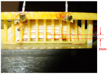
Yeah, the Audiostatic transformers were designed to provide an easier amplifier load with their panels having first segment capacitance of < 80pF. They did this by designing transformer with lots of leakage inductance by spacing the secondary away from the primary by nearly 2mm! (see pic)I'm currently using 2 x 1:75 (1:150 total) Audiostatic (secondhand) transformers. I bought them while they were affordable. I've read both positive and negative opinions about them, I would not expect them to saturate but I will try to get a scope to do measurements. At least bandwidth (high frequencies) is limited (they start to drop somewhere around 10kHz - 12kHz), I'm curious if this can be improved by a lower step-up ratio transformer - as long as there is still enough output. For instance 1:75 to 1:100 steup-up.
Normally you want to avoid spacing like this to minimize leakage inductance.
Full range transformers can be built with better HF performance having 1:75 to 1:100 ratio.
Careful design optimization is needed if you want 150:1 ratio with full bandwidth capability.
Attachments
Thanks again for the information Bolserst, I didn't notice the gap in the Audiostatic transformer
About two weeks ago I finished the second big panel and the problems with disappointing and smeared sound are gone! I didn't expect that. Most of the time it seems when I expect a positive change I get no change or a bad one - and when expecting no change I get a positive change when experimenting with the stats.
I still didn't experiment with damping materials as it takes some time and effort to attach them properly. But I start to appreciate the new big stats.
Last two nights I compared my DIY panels to a set of Final 0.3 hybrid stats that were stored in my house, they belong to a family member. I'm happy to conclude that my DIY stats sound better than the Finals: clearer, more detailed, tighter bass. The Finals sound a little dull and hollow compared to the big stats. But the Finals are still quite good in my opinion given their much smaller size. I'm not sure if they are very good reference speakers, I've read some posts about problems with wrong filters, dips in frequency etc., cheap woofer together with some very positive reviews. But for now I'm happy with my new stats.
I'm considering to build a (magnetic) woofer to supplement for low frequencies (below 100 Hz). I think it will be a sealed or transmission line woofer. Still not sure, but to me it sounds interesting. I'm wondering if those lower frequencies will add valuable musical information to the overall sound?
comparing the Final 0.3 hybrid stats to the new DIY panels (white stat in middle was not connected)
About two weeks ago I finished the second big panel and the problems with disappointing and smeared sound are gone! I didn't expect that. Most of the time it seems when I expect a positive change I get no change or a bad one - and when expecting no change I get a positive change when experimenting with the stats.
I still didn't experiment with damping materials as it takes some time and effort to attach them properly. But I start to appreciate the new big stats.
Last two nights I compared my DIY panels to a set of Final 0.3 hybrid stats that were stored in my house, they belong to a family member. I'm happy to conclude that my DIY stats sound better than the Finals: clearer, more detailed, tighter bass. The Finals sound a little dull and hollow compared to the big stats. But the Finals are still quite good in my opinion given their much smaller size. I'm not sure if they are very good reference speakers, I've read some posts about problems with wrong filters, dips in frequency etc., cheap woofer together with some very positive reviews. But for now I'm happy with my new stats.
I'm considering to build a (magnetic) woofer to supplement for low frequencies (below 100 Hz). I think it will be a sealed or transmission line woofer. Still not sure, but to me it sounds interesting. I'm wondering if those lower frequencies will add valuable musical information to the overall sound?
An externally hosted image should be here but it was not working when we last tested it.
comparing the Final 0.3 hybrid stats to the new DIY panels (white stat in middle was not connected)
Last edited:
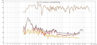
Can you provide REW curves for frequency and distortion, taken from your seat? That would be really helpful. I like 1/12 smoothing best.
B.
Hi, I did some measurements and for comparison I measured the Final 0.3 as well. I'm not sure I I measured distortion correctly. All measurements were made with mic at listening position.
An externally hosted image should be here but it was not working when we last tested it.
distortion DIY loudspeaker
An externally hosted image should be here but it was not working when we last tested it.
distortion Final loudspeaker
An externally hosted image should be here but it was not working when we last tested it.
frequency response Final loudspeaker
An externally hosted image should be here but it was not working when we last tested it.
frequency response DIY loudspeaker, no equalizing
An externally hosted image should be here but it was not working when we last tested it.
frequency response DIY loudspeaker, with equalizing
Last edited:
Beautiful. You've got great speakers. North of the bass, very orderly results. If you need additional electronic or acoustic tweaking to suit your ears, you are starting with a great system.
First chart is with EQ (which pushes up the distortion by pushing the speaker)?
Thanks for posting.
Here's a run of my system a year ago: Dayton-Wright cells in DIY frame, cone subs. Distortion looks a bit better but might be playing softer.
Ben
First chart is with EQ (which pushes up the distortion by pushing the speaker)?
Thanks for posting.
Here's a run of my system a year ago: Dayton-Wright cells in DIY frame, cone subs. Distortion looks a bit better but might be playing softer.
Ben
Attachments
Last edited:
Hi,
the speakers do indeed look fine, but I don't share the enthusiasm about the measured curves.
I'm not overly familiar with REW, but those soundcard/software based systems are basically all the same bunch and similar rules apply.
- ensure that the signal level going into the soundcard, i.e. the ADC of the card is sufficiently large, best as high as possible, just a tad before clipping. Around 70dB of SPL hints to a too low value, thereby loosing on signal-to-noise and resolution.
- have the system calibrated to be able to make consistant measurements that are comparable at least to your own. Comparing and (even worse yet) commenting on measurements of two systems without knowing the exakt conditions of both setups has more in common with fortune telling than decent evaluation
- have an idea (better though, a knowledge) about the behaviour of Your mic with regard to amplitude, phase and thd response. Well performing ESLs can easily reach down to thd levels considerably below the mic's/measurement setup. THD response levels of only 30-40dB below the amplitude response curve appear way too high for ESLs ... at least at 70-75dB SPL level.
- choose appropriatly scaled diagrams ... greater a 60dB range for the amplitude response diagram hides useful information and should be left to the marketing department of Bose and similars You and we at DIY prefer honest Information, don't we?
- for lows and mids measurements also do close-micced measurements with reduced clock rate (preferrably around 8kHz and lower). Frequency resolution is inverse proportional to the clock rate. The standard 48kHz clock already masks information in the lows.
So far the shown diagrams rather only proove the setup is basically functional.
Turning of a few tuning wheels is still required to extract consistant and reliable data.
jauu
Calvin
the speakers do indeed look fine, but I don't share the enthusiasm about the measured curves.
I'm not overly familiar with REW, but those soundcard/software based systems are basically all the same bunch and similar rules apply.
- ensure that the signal level going into the soundcard, i.e. the ADC of the card is sufficiently large, best as high as possible, just a tad before clipping. Around 70dB of SPL hints to a too low value, thereby loosing on signal-to-noise and resolution.
- have the system calibrated to be able to make consistant measurements that are comparable at least to your own. Comparing and (even worse yet) commenting on measurements of two systems without knowing the exakt conditions of both setups has more in common with fortune telling than decent evaluation
- have an idea (better though, a knowledge) about the behaviour of Your mic with regard to amplitude, phase and thd response. Well performing ESLs can easily reach down to thd levels considerably below the mic's/measurement setup. THD response levels of only 30-40dB below the amplitude response curve appear way too high for ESLs ... at least at 70-75dB SPL level.
- choose appropriatly scaled diagrams ... greater a 60dB range for the amplitude response diagram hides useful information and should be left to the marketing department of Bose and similars
You and we at DIY prefer honest Information, don't we? - for lows and mids measurements also do close-micced measurements with reduced clock rate (preferrably around 8kHz and lower). Frequency resolution is inverse proportional to the clock rate. The standard 48kHz clock already masks information in the lows.
So far the shown diagrams rather only proove the setup is basically functional.
Turning of a few tuning wheels is still required to extract consistant and reliable data.
jauu
Calvin
In a world of ultimate engineering perfection, this measurement technology falls short. But in a world of practical experience, the charts show that even with compromised tools, the results are really quite good and usefully characterize the system for present R&D purposes. Of course, results might be yet more remarkable if measurements were better... but results wouldn't be worse.So far the shown diagrams rather only proove the setup is basically functional.
B.
- for lows and mids measurements also do close-micced measurements with reduced clock rate (preferrably around 8kHz and lower). Frequency resolution is inverse proportional to the clock rate. The standard 48kHz clock already masks information in the lows.
jauu
Calvin
Hi Calvin,
Can you point me to a source that explains this phenomenon, for example, at 48kHz clocking?
I don't necessarily doubt it, but have never heard this claim, thanks.
*edit* are you talking about what shows in the graph alone? ..or the resolution of the frequencies themselves?
Last edited:
- Status
- This old topic is closed. If you want to reopen this topic, contact a moderator using the "Report Post" button.
- Home
- Loudspeakers
- Planars & Exotics
- DIY ESL