I got another n0ob Q. ")
How do you hook up the stators when you use powder coating?
I mean the actual connection. How to attach the wires to the stators?
And do you do it before or after the powder coating?
I have a couple of ideas of my own and I've seen a couple of examples but none that I have seen are really brilliant?
Holes in the stator/diaphragm seem like it would degrade the strength of the diaphragm?
Everyone seem to focus on the connection of the diaphragm so I'm guessing the stators are so easy it's hardly worth mentioning?
A good mechanical connection is all that is required on just a small area.
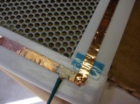
I had cut the material to the desired shape and dimensions after it was coated and had left a little tab to connect to.
I had also sealed the perimeter edges in clear silicone sealant this worked very good.
But has I had mentioned that the aluminium gets very brittle when flexed too much.
Because I did not properly mount the tabs, They eventualy broke off flush and there was nothing to connect to.
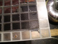
Since the edge of the wires where exposed where they broke off, I was able to remake the connection using a conductive glue such as NICKLE PRINT or a WINDSHIELD DEFOGGER REPAIR KIT to adhere piece of flexible wire to it.
A conductive glue made of white glue very heavily doped with graphite powder may work good aswell.
Although I did not try it because I still had some nickle print left over that was about to be completely hardened as it was quite old.
I did use it for the charge ring and it worked great.
I have not had a problem since.
You can get pretty ceative as to which mounting method to use.
I plan on incorperating a sandwhich type clamping system on the next build so that this little aggervation doesn't happen again.
It is not necessary to connect all of the wires at the edge of the stator (although I did do this on my very first painted version and it did not look very neat).
Due to the nature of wire mesh, all of the criss cross pionts is adequate to make sure that all the wires in the stator are connect to each other enregizing the complete panel.
I verified this with an ohmeter on the first one I did before I sealed up the edges and have had no problems with any of them including the painted ones.
This should help you get an idea.
If you like I can post some closeup pictures as there are some posted in the buried threads. jer
I had cut the material to the desired shape and dimensions after it was coated and had left a little tab to connect to.
I had also sealed the perimeter edges in clear silicone sealant this worked very good.
But has I had mentioned that the aluminium gets very brittle when flexed too much.
Because I did not properly mount the tabs, They eventualy broke off flush and there was nothing to connect to.
Since the edge of the wires where exposed where they broke off, I was able to remake the connection using a conductive glue such as NICKLE PRINT or a WINDSHIELD DEFOGGER REPAIR KIT to adhere piece of flexible wire to it.
A conductive glue made of white glue very heavily doped with graphite powder may work good aswell.
Although I did not try it because I still had some nickle print left over that was about to be completely hardened as it was quite old.
I did use it for the charge ring and it worked great.
I have not had a problem since.
You can get pretty ceative as to which mounting method to use.
I plan on incorperating a sandwhich type clamping system on the next build so that this little aggervation doesn't happen again.
It is not necessary to connect all of the wires at the edge of the stator (although I did do this on my very first painted version and it did not look very neat).
Due to the nature of wire mesh, all of the criss cross pionts is adequate to make sure that all the wires in the stator are connect to each other enregizing the complete panel.
I verified this with an ohmeter on the first one I did before I sealed up the edges and have had no problems with any of them including the painted ones.
This should help you get an idea.
If you like I can post some closeup pictures as there are some posted in the buried threads. jer
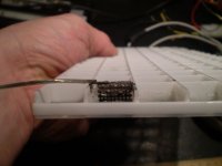
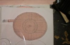
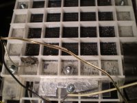
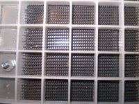
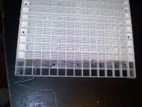
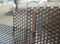
Here some pictures of a few connection methods that I have used so far.
The twisted wire method was used on my very first panels.
Before I had any idea of whether or not there would be any problems at the voltages that these panels run at.
So far I haven't had any problems as far as the connections are concerned.
Enjoy! jer
The twisted wire method was used on my very first panels.
Before I had any idea of whether or not there would be any problems at the voltages that these panels run at.
So far I haven't had any problems as far as the connections are concerned.
Enjoy! jer
Attachments
-
 back%20side.jpg33.1 KB · Views: 438
 -
 closeup%20of%20graphite%20charge%20ring.jpg37 KB · Views: 423
 -
 conections.jpg27.8 KB · Views: 419
 -
 diagpram%20side.jpg74.9 KB · Views: 418
 -
 HEADPHONE.jpg21.9 KB · Views: 419
 -
 nickle%20print%20repair.jpg67.4 KB · Views: 190
 -
 P1120327.JPG79 KB · Views: 172
 -
 P1120325.JPG75.6 KB · Views: 166
Thanks.
It's always nice to see how other people solve the problems.
Since I'll be using 1mm perf steel stators I'm considering soldering the wires to the edge of the stator?
Maybe solder a wire to the charge ring as well?This way I'll have three neat little wires to work with?
(I just started soldering mic-capsules, soldering to the edge of a stator should be a breeze?)
I have a roll of test lead wire that I got for the wiring and to build cables.
An other idea of mine is to run nylon bolts through the panels and use metal washers to make the connection but I'm not to fond of the idea of trying to punch holes in the panels?
My goal is to have "invisible" connections that I can hide them in the frame.
Thanks.
Since I'll be using 1mm perf steel stators I'm considering soldering the wires to the edge of the stator?
My goal is to have "invisible" connections that I can hide them in the frame.
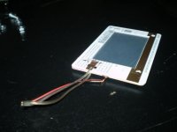
I would definitely solder the wires to the outside corners of the stators and you want to do that before you apply the stator coating. Mine are spray painted so I used 16 gauge stranded wire on the stators with standard insulation and there was no problem. However, standard insulation would melt in a powder coat oven so, if you will be powder coating your stators, you would need to use wire that has a high temperature silicon insulation. I would also solder the wire connection to the copper foil charge ring, but using a smaller diameter stranded wire (20-24 gauge). I used a wood chisel to notch out the inside of my wooden frames where the wires connect to the stators so the connections are neatly hidden inside the frames.
Use a good hot soldering iron with a large electrode for the stators and it takes a while to get the stator hot enough-- just press the iron to the stator as long as it takes to make the solder wet to the stator.
One more thing: When you strip back the wires to make the solder joint on the stators, make very sure there are no un-insulated portions of the wire hanging off the stator edge.
Last edited:
What kind of temperatures are we talking about?
Will it be hot enough to cause trouble if you use the wrong kind of solder?
I used a standard 30-watt soldering iron and rosin core solder... not a huge iron but not one of those with the tiny soldering tip for doing fine work either. PM me an email address and I'll send some photos.
Ah, I was referring to the powder coating process.
It would suck if one used solder with a low melting point and it suddenly fell off during the powder coating.
Good point! I hadn't consider that but now that you mention it, I just did a Wikapedia search; which says that 60/40 solder melts at about 370F and powder around 390F.
Options:
1) Attach steel tab using a torch and silver solder, which melts at 600F.
2) Solder the wire on after powder coating. Shoudn't be a problem as long as you don't expose any metal on the very edge of the stator. I think if you carefully grind thru the power coat near a corner, then solder the wire on there, that would be fine.
3) Mechanical connection like this one: http://www.diyaudio.com/forums/planars-exotics/181041-my-2-nd-esl-attempt.html
Last edited:
Ahh,Okay,I have the pictures of Mavrics connections ready aswell.
Another method you could use is to either spot weld or braze (high temp soldering) a small tab on the metal stator so that you can use a push on type connector like the ones commonly used on regular speakers.
Then you can simply tape the connector tab up with high temp tape to keep it from getting coated.
When using metal sheet be sure that you grind or sand off any and all sharp edges and points as these will cause an exteremly weak spots in the coating and they will leak and arc in those spots.
Mavric used some sort of sanding ball thingy on the surface and he said it work very nicely on the sharp edged side of the holes.
I have tried using nylon nuts and bolts and I had a hard time getting adeaquate pressure to secure the connections and evantualy stripped out every one I had.
I found that only the very large diameter ones worked okay but they were much to large for my appilcation and were quite costly besides.
jer
Attachments

Yes, if the stators are to be powder coated, I think the best solution would be to braze a tab on an outside corner before the powder coat. Any welding shop or auto body shop could braze the tab on for you in a couple of minutes.
If I were going to use a mechanical connection, I like the connection Roger (SM7UYJ) made on his speakers.... a hole countersunk on the inside surface to accept a flush metal bolt on each stator, attaching a steel tab on the outside. The spacer would cover the flush bolt head and that should work fine.
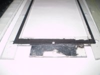
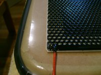
Attached is a photo of my stator being attached to the diaphragm while the diaphragm is on the bike-tube stretching jig. The wire was soldered on using a medium 30-watt soldering iron and .040 rosin core solder before the stator was spray painted with polyurethane.
If I were going to use a mechanical connection, I like the connection Roger (SM7UYJ) made on his speakers.... a hole countersunk on the inside surface to accept a flush metal bolt on each stator, attaching a steel tab on the outside. The spacer would cover the flush bolt head and that should work fine.
Attached is a photo of my stator being attached to the diaphragm while the diaphragm is on the bike-tube stretching jig. The wire was soldered on using a medium 30-watt soldering iron and .040 rosin core solder before the stator was spray painted with polyurethane.
Attachments
Hi, does anybody happen to know a source for 4-8 micron thick aluminixed mylar foil?
Regarding the speaker cable with ESL's, in theory, would you prefer low capacitance, high inductance speaker cable over "normally prefered" low inductance speaker cable? If ESL's impedance dips to say 1 ohm, would you prefer a cable with large area, for example 6-8mm2?
Regarding the speaker cable with ESL's, in theory, would you prefer low capacitance, high inductance speaker cable over "normally prefered" low inductance speaker cable? If ESL's impedance dips to say 1 ohm, would you prefer a cable with large area, for example 6-8mm2?
The most appropriate film I found was 12u metallized window film... hardware store, sun shields.Hi, does anybody happen to know a source for 4-8 micron thick aluminixed mylar foil?
Regarding the speaker cable with ESL's, in theory, would you prefer low capacitance, high inductance speaker cable over "normally prefered" low inductance speaker cable? If ESL's impedance dips to say 1 ohm, would you prefer a cable with large area, for example 6-8mm2?
Voltage at the amplifier output is rather low so the cable capacitance is low... hundreds of pF. Panel capacitance reflected to the ESL transformer's primary side is around few microfarads...
So, unless you are using direct drive low inductance is better.
I think the ESL57 uses 12 micron for the treble.
It uses 12 micron for the bass, 6 micron for the treble. But I've seen 'repairs' that use 20 micron on the treble panel for the diaphragm and dust covers...
It uses 12 micron for the bass, 6 micron for the treble. But I've seen 'repairs' that use 20 micron on the treble panel for the diaphragm and dust covers...
Have you heard one (12-20 micron)? Did it sound rolled off at the top?
Have you heard one (12-20 micron)? Did it sound rolled off at the top?
The 20 micron panel did not sound rolled off in an obvious way (and neither measured like it) but the sound was all wrong and had a lack of sparkle. It was so obviously wrong that when I heard it I thought "what the ***** is this??". Later I found it was 20 micron film (some polyolefin type).
- Status
- This old topic is closed. If you want to reopen this topic, contact a moderator using the "Report Post" button.
- Home
- Loudspeakers
- Planars & Exotics
- DIY electrostatic speakers for dummies