Here's a useful link which just got posted up in the AudioSector area - useful to have here too. Its about choosing resistor values on TDA1543s.
http://myweb.tiscali.co.uk/g8hqp/audio/TDA1543IV.html
http://myweb.tiscali.co.uk/g8hqp/audio/TDA1543IV.html
Thanks for the link. Would this be the same for the TDA1543A? as the TDA1543 chip is hard to get hold of. Earlier in the thread, bcmbob posted a link to an eBay item which was an optical to SPDIF converter, would this give a deteriorated signal over a direct connection to the DIR receiver from an optical receiver?
Ok. The second question.....
bcmbob posted a link to an optical -> SPDIF converter on eBay...
TOSLINK Optical Input to S/PDIF Module | eBay
I have 2 ways of getting an optical signal to my DIR9001 receiver board.
1. Use the above optcal -> SPDIF board... the optical signal is taken, then converted to SPDIF and then into the front end of the DIR9001 receiver board I have purchased.
2. Use a TORX147, I could simply connect the output of it to pin 20 of the DIR9001.
Would option 1 be as good as option 2, as option 1 has a lot more circuitry than option 2 and normally I find simplicity is the best route to take.
Right. I have the DIR9001 board coming, a transformer, a TORX147 and I am developing a PIC microprocessor (PIC16F690) to put into the DAC/Pre amp enclosure so I can have Optical, SPDIF and 2 x analogue input, IR controlled etc. But what is the best way to ground all of my circuits? In my amp, I have a mains protection ground, with a star power ground connected to it with a 10ohm resistor in parallel with 2 back to back diodes and then the same from there to the star audio ground.
In my DAC/pre amp, I will obviously have the ground from the DIR9001 receiver, the Toslink receiver, the PIC board, the relay board and the grounds from the analogue inputs and output.
Sorry again for all the questions, I will obviously be experimenting quite a bit, but it would be good to have a head start")
I also noticed that each power supply from the regulator chips in most of the circuits use in line inductors. Is there any particular size these should be? Different sites show different sizes, does this need to be calculated, or is there a kind of general rule-of-thumb?
In my DAC/pre amp, I will obviously have the ground from the DIR9001 receiver, the Toslink receiver, the PIC board, the relay board and the grounds from the analogue inputs and output.
Sorry again for all the questions, I will obviously be experimenting quite a bit, but it would be good to have a head start
I also noticed that each power supply from the regulator chips in most of the circuits use in line inductors. Is there any particular size these should be? Different sites show different sizes, does this need to be calculated, or is there a kind of general rule-of-thumb?
Last edited:
Grounding is an art so there's no simple way to describe the 'best' way to do it - its rather like asking 'what's the best way to paint a portrait' The general principle to apply though is 'small loops good, large loops bad' and realize that all wires are effectively inductors.
If you look at my first schematic you'll see I've gone for a two level grounding system. The dirty grounds go to the lower level star and the clean ones go to the next level. Your DIR9001 board will have a dirty ground if you use the coaxial SPDIF, but if you only use optical then it counts as clean. The other dirty grounds are the power supply input and the analog output grounds.
Another question to get clear in your mind is whether a ground is being used to supply power, or as a signal reference, or both. In many cases its both - for example the ground to your DIR9001 board. In such cases you're best arranging the supply so that only DC flows through the ground, no HF. That's where shunt regulators are valuable - they can help resolve the HF currents locally. And that's why inductors are used - to raise the power supply impedance at HF so higher frequencies are encouraged to travel around the smaller, more local loop.
As to the size of the inductors - first they need to be able to handle the DC supply currents without saturating. Second they need to have a high enough SRF (self resonant frequency) so as to block circulating HF currents. I myself prefer to use ferrite beads rather than inductors - they act rather like a lossy inductor, so absorb noise rather than merely block it. A pure inductor, having much lower loss, can resonate, something its best to avoid - so if you use inductors, put a resistor in parallel to damp down any tendency to peaking.
The general principle to apply though is 'small loops good, large loops bad' and realize that all wires are effectively inductors.If you look at my first schematic you'll see I've gone for a two level grounding system. The dirty grounds go to the lower level star and the clean ones go to the next level. Your DIR9001 board will have a dirty ground if you use the coaxial SPDIF, but if you only use optical then it counts as clean. The other dirty grounds are the power supply input and the analog output grounds.
Another question to get clear in your mind is whether a ground is being used to supply power, or as a signal reference, or both. In many cases its both - for example the ground to your DIR9001 board. In such cases you're best arranging the supply so that only DC flows through the ground, no HF. That's where shunt regulators are valuable - they can help resolve the HF currents locally. And that's why inductors are used - to raise the power supply impedance at HF so higher frequencies are encouraged to travel around the smaller, more local loop.
As to the size of the inductors - first they need to be able to handle the DC supply currents without saturating. Second they need to have a high enough SRF (self resonant frequency) so as to block circulating HF currents. I myself prefer to use ferrite beads rather than inductors - they act rather like a lossy inductor, so absorb noise rather than merely block it. A pure inductor, having much lower loss, can resonate, something its best to avoid - so if you use inductors, put a resistor in parallel to damp down any tendency to peaking.
Grounding, can be an art but it is also science, Henry Ott is probably the BEST source of information regarding grounding issues.
Technical Articles/Talks
His book "Electromagnetic Compatability Engineering" is one of the best books you can buy if you want to explore grounding further than the nyths and mysteries that souround it.
Technical Articles/Talks
His book "Electromagnetic Compatability Engineering" is one of the best books you can buy if you want to explore grounding further than the nyths and mysteries that souround it.
Thanks again everyone. I've been looking at inductors. This 47uH has a min Q factor of 30 and 1.1A
POWER INDUCTOR RADIAL LEADS - VALUES 22uH TO 12mH x 3 | eBay
Is this the kind of thing I am after? If so, what power rating resistor would I put in parallel with it?
POWER INDUCTOR RADIAL LEADS - VALUES 22uH TO 12mH x 3 | eBay
Is this the kind of thing I am after? If so, what power rating resistor would I put in parallel with it?
The choice of inductor depends on what you're going to power through it. A 1.1A rated one is overkill for a DAC - unless you've decided on 20 TDA1543s in parallel Its worth noting that above the resonant frequency the inductor looks like a capacitor so won't do any filtering - a ferrite can be used (in series with the inductor) to take the filtering effect to higher freqs. Or alternatively a lower value inductor with a correspondingly higher SRF. Putting inductors in series to improve the filtering is akin to putting different value caps in parallel to improve the decoupling.
The resistor power rating is very low because its only going to absorb any power at RF where hopefully you haven't got much energy sloshing around. 1/8W will be more than adequate.
Its worth noting that above the resonant frequency the inductor looks like a capacitor so won't do any filtering - a ferrite can be used (in series with the inductor) to take the filtering effect to higher freqs. Or alternatively a lower value inductor with a correspondingly higher SRF. Putting inductors in series to improve the filtering is akin to putting different value caps in parallel to improve the decoupling.The resistor power rating is very low because its only going to absorb any power at RF where hopefully you haven't got much energy sloshing around. 1/8W will be more than adequate.
I am going to run 8 x TDA1543As in parallel, so maybe the 1.1A inductor is a bit overkill. I will probably get 500mA rated ones and a 1K resistor in parallel. Anyway, I'm waiting for loads of bits to turn up from Hong Kong etc. so it'll be a week or so until I can start to experiment
Please excuse me if I missed something, but I'm not sure if you are attempting a scratch build or planning to use/modify the unit in the first post on this thread. That one appears to have optical on-board. Please clarify.
Sorry bcmbob, I missed your post
I am basically building DAC pre-amp to go with my Gainclone amp. I have bought the IDR9001 receiver module as mentioned earlier. Along with this board, there will also be my power supply, relay board (to select input sources), DAC (8 x TDA1543A), lightspeed attenuator board and my control board with my PIC16F690 being used to move a volume pot up and down and to select the inputs. There will be a 2 bit greycode rotary encoder to select the input as well as IR control.
The lightspeed attenuator PCB is already made and is currently in my Gainclone. All of the other PCBs will also be home made using the 'Laser toner & photo paper' tecnique.
abraxalito, you mentioned earlier that pins 7 should be left floating when paralleling DACs, so does that mean that only one of the DACs has pin 7 connected to ground via the resistor?
I have designed in Eagle a 8 x parallel DAC board where at the moment all of the pins are commoner together and all fed via the same 330R resistors. I jet re-read this thread and you said about feeding each DAC with separate 330R resistors, so I guess I will have to change the design a bit.
Here is a rough PCB design (note that the layout is a bit of a copy from a link shared earlier in the thread)
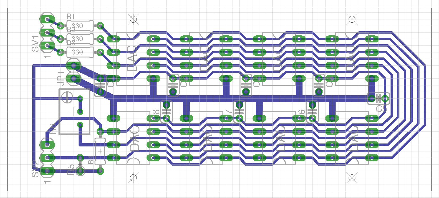
I have designed in Eagle a 8 x parallel DAC board where at the moment all of the pins are commoner together and all fed via the same 330R resistors. I jet re-read this thread and you said about feeding each DAC with separate 330R resistors, so I guess I will have to change the design a bit.
Here is a rough PCB design (note that the layout is a bit of a copy from a link shared earlier in the thread
)
By pin7 floating I meant that it shouldn't be paralleled - give each chip its own resistor. Given that you have a compact layout I'd not worry much about having resistors on each chip's digital inputs. What I do worry about though is sharing grounds - when I parallel up DACs I wire the 0Vs point to point to a star earth. I agree that's a bit tricky on a PCB rather than with 3D wiring, but its one of the ways I've found that gets good sound. Also use one ferrite bead per chip on the +ve supply.
- Status
- This old topic is closed. If you want to reopen this topic, contact a moderator using the "Report Post" button.
- Home
- Source & Line
- Digital Line Level
- DIY DAC....is this any good