john65b said:I changed a few resistor and stacked three more TDA1543 a la Kusinoki design and it sounds much better than as bought.
Do you have any pictures, and what did you use for a heatsink?
I will have to remember what the resistor values were - there is a TDA1543 java app that will let you choose teh values for a particular input voltage , output voltage, etc...
See here
Look for the I/V Resistor section and a link from Thorsten Loesch.
Attached is the calculator for setting your resistors. plaay around with it...like I said, I like the sound now better than ever, but still lacks compared to a couple others I have. Some really love this Kusinoki setup.
An externally hosted image should be here but it was not working when we last tested it.
An externally hosted image should be here but it was not working when we last tested it.
See here
Look for the I/V Resistor section and a link from Thorsten Loesch.
Attached is the calculator for setting your resistors. plaay around with it...like I said, I like the sound now better than ever, but still lacks compared to a couple others I have. Some really love this Kusinoki setup.
Attachments
Hi John
thank you for your precious information.
As I can see you are using 4 pcs. TDA1543. What is the difference to single piece?
I have got that one!
thank you for your precious information.
As I can see you are using 4 pcs. TDA1543. What is the difference to single piece?
I have got that one!
An externally hosted image should be here but it was not working when we last tested it.
Hey Tolu,
That´s exactly the same DAC as I have on the bench. Get rid of those output-caps in favour of some good plastics. Also, why not try ECs biasing method by adding a 3V Lithiumbattery and two new 680ohm bias-resistors?
My idea was to add a Schade-connected 2SK170 onboard. Then the caps should be after the FET.
Hey Lars,
did you do the EC mod so far and/or added the proposed JFET stage?
I'm not sure to invest more time and money in this cheap 20 years old silicon after I did some listening yesterday. I don't expect a big change to the good. What I like is a nice sound stage, a well top end and great dynamics. That is all missing with this chip. It's all a trade off, I think. I haven't found my perfect DAC or CDP so far.
But please keep me informed about your developments.
did you do the EC mod so far and/or added the proposed JFET stage?
Will try the EC-mod. But as I don´t need extra gain I am thinking of another FET-solution with less gain.
For $2.50 a chip, stack the TDA1543 and the sound will definitely improve. You will have to swap a couple I/V resistors to correct the voltage and output (the attached calculator in my post will help determine the values). It made it into an OK DAC to a very good DAC. Not Great but very good. I just stopped playing with it a few years ago in favor of a 24 bit CS4397/CS4398.
Like I said, there are many that Love this TDA1543 stacked 4X and 8X. Improves all the shortcomings quite a bit.
I don't know if its the same, but isnt the venerable TDA1541A and TDA1543 about the same age? 20 or so year old design? I would love to buy/build a Double craown based TDA1541A...of course these are not 24 bit (16Bit?)
Actually, if anyone is interested, it is for sale with 1A wall wart.
Tolu,
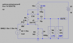
before you dump the 1543 you could do a minor tweak. Cut the two 2200p caps(green squares) and parallell the 1k I/V resistors with 5,6k each. If we assume 5V loading the I/Vs should be 860 ohm together with 1k ref.
Next step is to change the output lytics with plastics.
Below is an idea of a buffer where the reference-voltage is fed via the 680ohm feedback-resistor. It sims great due to the "triodish" way of working with just above 12dB gain. Zout is ca 200ohm
Attachments
questions re 1543 dac and trends UD10
I have just got hold of the mini dac board and intend to do some mods re EC designs and the power supply. This DAC will be fed by my trends UD10 and feed the analogue into a set of gainclones.
So a couple of questions, I can feed the DAC with a 75 ohm coax, but it is well within reason for me to remove the trends UD10 from its box and mount it next to the DAC in the same case. IN this situation I imagine I could do away with the cable and directly connect the two via a very short wire with an external output on the case should I wish to use the Trends with some other DAC later on. Now if I did this what would I need to do at the trends UD10 end of things and the dac end of things.
I not fully up to speed on digital signal transfers but I imagine the bits for the 75 ohm connection are there to ensure a jitter free transfer via the cable, so if the cable is eliminated then the bits relating to it can also be eliminated? Or should I just use a really short cable (I would have to make this). My research has indicated that 1.5 metres is the ideal length normally to lower jitter issues but in this application there is probably some other ideal length if the coax linkage is kept.
The other question relates to the output caps, I would replace these, however in my setup the DAC will feed into a system which is designed as a complete system, in other words there is no mix and match of components so I know the clones have the ideal input caps attached to them etc and none of this will be changed, this DAC will only serve this system. So can the output caps on this board and the resistors that go to ground after the caps be removed or will this upset the operation of the I/V somehow.
Re: questions re 1543 dac and trends UD10
Yes, as long as your amps have input caps you can remove the DAC output caps and resistors and the I/V will not be affected. However, if you are switching between input sources to your amp you will get a loud pop through your speakers when you switch to the DAC because of its output DC charging the input caps.
Zero One said:
The other question relates to the output caps, I would replace these, however in my setup the DAC will feed into a system which is designed as a complete system, in other words there is no mix and match of components so I know the clones have the ideal input caps attached to them etc and none of this will be changed, this DAC will only serve this system. So can the output caps on this board and the resistors that go to ground after the caps be removed or will this upset the operation of the I/V somehow.
Yes, as long as your amps have input caps you can remove the DAC output caps and resistors and the I/V will not be affected. However, if you are switching between input sources to your amp you will get a loud pop through your speakers when you switch to the DAC because of its output DC charging the input caps.
Hi Revintage
I can see you point re vol control however there is no volume control as such, the dac and phono pre amp feed the amps direct, volume is controlled via LPad system on the output of the amps, sounds odd I realise but it actually sounds quite wonderful and no problem with output levels as the speakers are 100db efficient.
Each Gainclone module has its overall gain set to suit the speaker unit it is driving, with 4 amp modules per stereo side.
One thing I would like to get is an output as close as possible to the phono pre amp, which is about 0.6v, this will help keep things on an even keel.
I am assuming the output on this dac will be somewhere a bit under 0.5v in EC modded form is this correct?
If I were to raise the bias battery to 3.6v and the resistors to 820 ohm would I end up with a similar output to the Phono Pre?
Hi revintage, you may have to guide me on this, the amps are non inverting and I think that the input impedance is calculated as the resistor value that goes from the non inverting input to ground? This being the case it is 1M.
This value is not fixed in stone it is easy enough to change as I am currently running the test modules and are about to build the final versions.
While we are here there are two small value caps t (2200nf) that run from the output lines after the I/V resistors to ground on the dac, no other schematics for similar dacs show the usage of these, any ideas why they are there? I am assuming they can safely be deleted.
Tolu said:Hey Lars,
did you do the EC mod so far and/or added the proposed JFET stage?
I'm not sure to invest more time and money in this cheap 20 years old silicon after I did some listening yesterday. I don't expect a big change to the good. What I like is a nice sound stage, a well top end and great dynamics. That is all missing with this chip. It's all a trade off, I think. I haven't found my perfect DAC or CDP so far.
But please keep me informed about your developments.
Strange, I don't find this dac lacking in dynamics. In fact, I found tda1543 has better dynamics than quite a few dac. I would definitely mod this dac.
Change the output cap, Vishay mkt1822 is only few dollar from Farnell.
The decoupling of this dac is not very good. Rubycon ZL is fairly cheap.
Let it burn in a while.
Implementation makes a big difference for this dac.
Further questions at the pointy end of things.
Looking at ECs circuit layout it seems there is a 4700uf cap on the 5v supply to the 1543 chip, the dac board has only 100uf, I assume it works fine as is, but is there a likely benefit in going to a higher capacitance cap with a small bypass. This is easy to do, I could solder a 1000uf smd under the chip plus 0.1 smd tant or similar.
It also appear 2x 3v lithiums are used instead of one, ie one per channel, is there a benefit to this over one to justify the effort, happy to do so if it is better.
Cheers
Zero One

- Status
- This old topic is closed. If you want to reopen this topic, contact a moderator using the "Report Post" button.
- Home
- Source & Line
- Digital Line Level
- Diy-dac 1543