The cap is still there.
The difference here is that there is no balanced volume control.
In the Pass DAC there is a volume control that has a low Resistance value.
That means to block DC without the High Pass filter getting into Audio you need a large capacitance.
In my Version I only have a 100K resistor at the output so you only need 4,7uF Cap there. For better quality I use an Audyn Cap MKP Capacitor.
Important notice !!!!
Hi everbody.
I want to thank everbody for the great interest in the pcbs.
I have sent most of you an email with an order form you have to fill out with your address and what you want to order say I can tell you what it will cost, how much the shipment is, how you can pay me and some info on parts.
If you haven´t received an email from me and you are interested in the boards please contact me at :
promitheus@web.de
or through diyaudio.
Greetings Promitheus
I want to thank all those who have ordered. I still have a few pcbs left so if anyone is interested please mail me for more information.
For those who have already ordered I am gathering the parts they want and I will start sending everything end of next week.
Stay posted.
For those who have already ordered I am gathering the parts they want and I will start sending everything end of next week.
Stay posted.
Blitz did you get in contact with me?
I have sent all the boards and parts to those who paid.
I still have a few boards and parts. So if you are interested I can send you an order form with all instructions and prices.
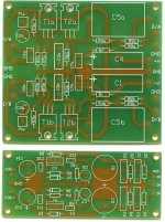
I am making a set of boards for myself and I will post photos soon.
I have sent all the boards and parts to those who paid.
I still have a few boards and parts. So if you are interested I can send you an order form with all instructions and prices.
I am making a set of boards for myself and I will post photos soon.
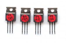
The IRF610 I matched look like this.
All are in quads but the ones with the same letter are better matched.
First I measured the Vgs of every one at the same temperature and same time. After that I made groups that exactly the same voltage to the 3rd digit for instane 3,917 Volt. Thats what the 2 numbers on the Fets are. They are the last 2 digits of the first measurement.
After that I put 2 Mosfets at a time on the JIG with presisions resitors and measured the voltage difference between the 2 Vgs. You get a better measurement this way bacuase the Multimeter is scaled at mV.
The pairs are matched to better as 5mV normally at 2-3 mV.
Thats better as 0,1% tolerance.
Attached is a picture of what a quad looks like.
Attachments
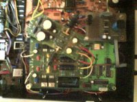
One is up and running now. Just for testing. All seems to work well, but i only listened for a moment (it's getting late here and it's not great to run a class a amp with these temperatures )
)
Connected just one pcb, so no balanced mode. What you see in the picture (top2bottom):
cd650 main pcb
display powersupply
d1 powersupply
d1 stage
dac underneith (two tda1541 full balanced, clock on dac with feedback to player).
I'll stick to this for a moment and concentrate on the preamp now.
Using a meridian 201 for the moment and it's not that great cmos logic for volumecontrol....
Then a redesign of the dac pcb and stuff all in the cd80.
The things sticking into the regulators are hf diodes with a heatsink, the lm's were getting a bit hot (anyone just running them without heatsinks?)
Thanks to promitheus and the one and only.
)Connected just one pcb, so no balanced mode. What you see in the picture (top2bottom):
cd650 main pcb
display powersupply
d1 powersupply
d1 stage
dac underneith (two tda1541 full balanced, clock on dac with feedback to player).
I'll stick to this for a moment and concentrate on the preamp now.
Using a meridian 201 for the moment and it's not that great
cmos logic for volumecontrol.... Then a redesign of the dac pcb and stuff all in the cd80.
The things sticking into the regulators are hf diodes with a heatsink, the lm's were getting a bit hot (anyone just running them without heatsinks?)
Thanks to promitheus and the one and only.
Attachments
No,
Not yet. PCB for the preamp is shipped today by olimex.
So in a week or so i should have my tube preamp running again for some serious listening.
Also keep in mind that the powersupply for the DAC (and the XO on there) are still coming from the cd powersupply. Still much to improve, keeps me busy
Not yet. PCB for the preamp is shipped today by olimex.
So in a week or so i should have my tube preamp running again for some serious listening.
Also keep in mind that the powersupply for the DAC (and the XO on there) are still coming from the cd powersupply. Still much to improve, keeps me busy
- Status
- This old topic is closed. If you want to reopen this topic, contact a moderator using the "Report Post" button.