New thread...
http://www.diyaudio.com/forums/tubes-valves/206787-micro-programmable-tube-tracer-tester.html
I added the link in case someone comes along in the future reading this thread and wonders what happened to the new proposal.
I'll also add a link to the new thread for ref to this one.
http://www.diyaudio.com/forums/tubes-valves/206787-micro-programmable-tube-tracer-tester.html
I added the link in case someone comes along in the future reading this thread and wonders what happened to the new proposal.
I'll also add a link to the new thread for ref to this one.
Without opening up your soundcard -- you can use an RMS converter which renders the output to DC. Very good products from Analog Devices, Linear Tech and ThatCorp. It'll spare you the heart-break of a fried sound card.
With regard to driving a MOSFET -- you're not going to do it easily with a DAC -- the best way is to use 2 MOSFETs, the first as an inverting amplifier. IRFPG40 is a $5 part which I used for the AX article 9 years ago. I posted the schematic at #30 of this thread.
I like the enthusiasm for the Arduino -- I prefer PICs since they're so cheap and fast. I've also used the USBMicro adapters which program in C.
New thread...
http://www.diyaudio.com/forums/tubes-valves/206787-micro-programmable-tube-tracer-tester.html
I added the link in case someone comes along in the future reading this thread and wonders what happened to the new proposal.
I'll also add a link to the new thread for ref to this one.
Thanks for the xreference. I wanted to start a new thread because I have a lot of information and don't want to hijack this one. I was waiting to come out with it until I had more defined but it seemed like a good time to join the conversation

Agree with you all, a digital approach to the curve tracer would open a new dimension to this, but requires a lot of time in programming in addition to the HW. I'm not against it but despite having programmed in Assembler for HC11, PIC, DSPs and C a long time ago, It would be a titanic task for me to embark on
Hopefully can get the sync and everything completed at some point to play with this tracer....
I will definitely join a PiC, Ardunino or whatever project once someone gets it working first!
Thanks
Ale
Hopefully can get the sync and everything completed at some point to play with this tracer....
I will definitely join a PiC, Ardunino or whatever project once someone gets it working first!
Thanks
Ale
I use two transformers, one for HV where i use a bridge rectifier to make the Plate drive signal. I also use a small 6.3 volt transformer that i use for the grid step generator, I pass the output thru the phase adjust and then to the schmitt trigger. I dont use a rectifier for the step generator. If you use your transformer just for the step generator then you can bypass the bridge rectifier and you should then get the 200hz without modifying the divider on the PLL.
An externally hosted image should be here but it was not working when we last tested it.
Fixed PLL divider now to 2. I get a clock signal of 200Hz. Now I can fit two grid steps in the 100Hz cycle
Still may need to add the phase adjustment RC network.
Will get the driver boards and hopefully do some tests soon
Attachments
Hi Alfredo,
The reference signal in the previous post is the input to the comparator. I'm actually using a back to back transformer to get 220Vrms to drive the anode.
Today I etched the grid driver. See attached. I can get 15V peak to peak biased from +5V to -80V. I will increase the gain of the grid driver as 15V seems a bit low when it comes to power triodes...
I will post the updated diagram when I get the chance to draw the updates.
Thanks
Ale
Attachments
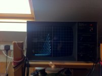
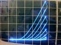
Great progress today! Hooked everything up in my messy workbench with a bit of long cables and precarious connections but anyway: it works!
I may need adding the phase correction as Alfredo suggested, but have a look at the attached image. Plotted four pairs of 46 in triode mode with great linear curves....
Cheers,
Ale
I may need adding the phase correction as Alfredo suggested, but have a look at the attached image. Plotted four pairs of 46 in triode mode with great linear curves....
Cheers,
Ale
Attachments
Looking goog Ale,
You also may want to add some resistance in series with the HV plate drive to limit the current and not drive the tube as hard. You could use the same values as in the Tek 570 schematic.
What kind of x-y display is that? It has a big screen. Or is it the picture that makes it look large?
Alfredo
You also may want to add some resistance in series with the HV plate drive to limit the current and not drive the tube as hard. You could use the same values as in the Tek 570 schematic.
What kind of x-y display is that? It has a big screen. Or is it the picture that makes it look large?
Alfredo
Hi Alfredo,
I don't have the Tek 570 schematic, can you send it to me please?
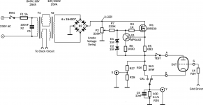
I'm using a current limiter in the Mosfet source follower as per circuit diagram attached. Currently is set to 100mA and you can see that the trace becomes brighter on the scope screen when this limit is reached.
How can you improve the PLL frequency stability? I believe that is part of the headache of synchronisation of this design.
I have a slight issue which is the trace appears to be double. I guess is this a result of lack of sync or do you think there is some other problem here?
Cheers,
Ale
I don't have the Tek 570 schematic, can you send it to me please?
I'm using a current limiter in the Mosfet source follower as per circuit diagram attached. Currently is set to 100mA and you can see that the trace becomes brighter on the scope screen when this limit is reached.
How can you improve the PLL frequency stability? I believe that is part of the headache of synchronisation of this design.
I have a slight issue which is the trace appears to be double. I guess is this a result of lack of sync or do you think there is some other problem here?
Cheers,
Ale
Attachments
I don't have stability issue with my PLL. You could play with the RC values as per the datasheet to improve the lock response. Dont know if the rectification makes a difference to the stability of the schmitt trigger. My schmitt trigger puts out a stable 50% duty cycle 60hz signal when fed by the low voltage 60hz sine wave.
There shouldn't be a double trace at all. Have you tried doing the phase adjustment?
Tek 570 Manual Link
There shouldn't be a double trace at all. Have you tried doing the phase adjustment?
Tek 570 Manual Link
I think the values of the RC network may vary by the specific version of the 4046 pll. I am using a texas instruments 4046BE and the values are also Vdd dependent. I use around 15V. I have not really played much with it.
As far as the phase pot it is a regular linear pot. The behavior I have seen is that it is calibrated just one time.
As far as the phase pot it is a regular linear pot. The behavior I have seen is that it is calibrated just one time.
I have been busy today building the power supply sections. Built it with parts I had in the bin.
The +-100 is unreg as the LME doesn't really care (from what I have seen).I am using two 70V power transformers connected in series, using the connection as center tap where I will inject the bias.
The +- 14V is a regulated power supply with a LM317 and a LM337.
The Bias supply is a variable regulated supply with a TL783. The whole thing is floating so I hope I can use it as a negative supply.
I still have space for a regulated Screen supply. For now I will use the bench to supply screen voltage if testing Pentodes.
I need to think on the physical layout as well now. I have an old breadboard box I built with many sockets and 2mm banana plugs and sockets to play around. I will probably look at doing the same in a large aluminum case to fit all the pcbs and trafos.
Also have a bunch of ferrite beads to use and keep short wires to get the best image out in the CRT
I'm using a 10 ohm cathode current sense resistor bypassed by a 10n capacitor. Then feeding the differential voltage to the similar dif amplifier that Goote posted early in this thread. This 10x amplifier provides also an inversion of the signal as my oscilloscope didn't have one...
Which connections do I need to look closely to minimise noise / image distortion?
Had a terrible day today: XY scope died and managed to fix it and re-calibrate somehow. I found that is the scope circuit which is creating the double traces. No idea of what could be, but probably will require a lot of effort to find the root cause. Considering that it costed me only 25 pounds I'd probably leave it as it is...
The other thing I found was that it takes some time for the PLL to stabilise. Not sure if this is normal or expected, however when I do vary the grid signal driver it appears to have some interference with the PLL and takes a bit of extra time to get back in sync.
Any idea how can improve the PLL stability? May need to read the datasheet though...
Here is a final test with a 26 DHT valve...
cheers,
Ale
Attachments
Any idea how can improve the PLL stability? May need to read the datasheet though.
Ale
You have to optimize the filter values in the feedback loop from the phase comparator. Helps if you have a network analyzer!
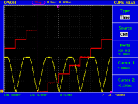
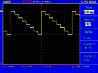
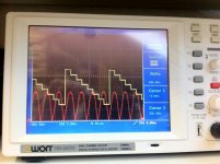
Today I finished the driver board and did a quick test. BTW, a few weeks ago I received a new Rigol DS1102E oscilloscope. I like it a lot. The display is not as clean as with the Analog scope but it has many nice features, especially acquiring the data for the computer. It is what I am planning to use to capture the curve data.
A 15 Volt PP signal, 1 Volt/step
A 150 Volt PP signal, 10 Volt/step
Alex, I also played a little with the PLL and the filter. I found that if you add a resistor of 100K-300K above the capacitor that it locks very quickly.
pin 13-------
|
4.7M
|
pin 9--------
|
100K-300K
|
1uf
|
gnd
(I cant get the above text drawing to display properly, doesn't take spaces. Hopefully you get the idea)
hope it works
Tomorrow I try with some tubes.
Alfredo
An externally hosted image should be here but it was not working when we last tested it.
A 15 Volt PP signal, 1 Volt/step
An externally hosted image should be here but it was not working when we last tested it.
A 150 Volt PP signal, 10 Volt/step
An externally hosted image should be here but it was not working when we last tested it.
Alex, I also played a little with the PLL and the filter. I found that if you add a resistor of 100K-300K above the capacitor that it locks very quickly.
pin 13-------
|
4.7M
|
pin 9--------
|
100K-300K
|
1uf
|
gnd
(I cant get the above text drawing to display properly, doesn't take spaces. Hopefully you get the idea)
hope it works
Tomorrow I try with some tubes.
Alfredo
Last edited:
- Status
- This old topic is closed. If you want to reopen this topic, contact a moderator using the "Report Post" button.
- Home
- Design & Build
- Equipment & Tools
- DIY Curve Tracer