Hello Hugh,
I wrote a long reply and then my computer went down, again, losing all that was written, so here is a precise of what I wrote:
I question (anyone) who tries to damp thick materials with cld. Cld is only used in situations where thin metal/plastic/honeycomb structures need damping, where thin layers of a viscoelastic material is contrained by a thin layer of a material, usually the same on similar to the first layer (that to be damped). Cld relies on bending to be effective, although we are talking about microscopic levels of displacement.
So if you want to have a damped material to make a plinth, choose a material which has high intrinsic damping, like Panzerholz or other engineered woods known to have good damping.
If you are measuring a test sample of material, it has to be cut very precisely, so all edges are square. If any dimension is variable, resonance peaks may be broad, and unrepresentative.
You want to place your accelerometer in the middle of the test piece. This is where the largest displacements are. Also, ensure your accelerometer uses either the X or Y direction, as the Z direction has a much lower bandwidth. The X and Y directions are bandwidth limited by on-board resistors/capacitors, and must be compensated for (in software is easiest). Look at Audacity, and under 'effect' click on Equalization. Construct a equalization curve which runs from 50Hz up to 10kHz, at 6 dB/Octave (to about 40 dB). I have it level from 50 Hz to 40 Hz (0 dB) then -30dB at 20 Hz. After you have named and saved, you can apply that filter to your waveform. Try to record the waveform at the highest resolution possible. You can look at your recorded waveform with the high pass and low pass filters, thereby choosing to look at just one frequency with tiny band-pass (essentially one frequency). That can be quite illuminating!
I don't recommend marbles et al for producing vibrations. I use a small hammer, which has a selection of heads, which are changeable, including brass, iron and acrylic (Watchmakers Jewellers Mallet Hammer, according to ebay). I usually use the iron one, as it has a round tip. It doesn't take long before consistent hits can be made. And it isn't necessary to have perfectly consistent force applied. Try to bash the test piece about 8 or 9 times, and discard the worst ones, leaving 5 or 6 on which to work.
In your last pic, I'm not sure your first peaks are the fundamentals in each case. The fundamental resonance is often the highest, but not always. You really need better test samples.
Also, not so relevant to the work you have done so far, but natural wood is notoriously anisotropic, meaning you will get different results depending on which direction the vibrations are oriented. Also, the moisture content will have an affect on damping factor measurements, as well as any surface/internal treatments.
I hope that this is helpful, but don't hesitate to ask if there is anything else you want to know. And keep up the good work
Last edited:
So if you want to have a damped material to make a plinth, choose a material which has high intrinsic damping, like Panzerholz or other engineered woods known to have good damping.
You want to place your accelerometer in the middle of the test piece. This is where the largest displacements are. Also, ensure your accelerometer uses either the X or Y direction, as the Z direction has a much lower bandwidth. The X and Y directions are bandwidth limited by on-board resistors/capacitors, and must be compensated for (in software is easiest). Look at Audacity, and under 'effect' click on Equalization. Construct a equalization curve which runs from 50Hz up to 10kHz, at 6 dB/Octave (to about 40 dB). I have it level from 50 Hz to 40 Hz (0 dB) then -30dB at 20 Hz. After you have named and saved, you can apply that filter to your waveform. Try to record the waveform at the highest resolution possible. You can look at your recorded waveform with the high pass and low pass filters, thereby choosing to look at just one frequency with tiny band-pass (essentially one frequency). That can be quite illuminating!
I don't recommend marbles et al for producing vibrations. I use a small hammer, which has a selection of heads, which are changeable, including brass, iron and acrylic (Watchmakers Jewellers Mallet Hammer, according to ebay). I usually use the iron one, as it has a round tip. It doesn't take long before consistent hits can be made. And it isn't necessary to have perfectly consistent force applied. Try to bash the test piece about 8 or 9 times, and discard the worst ones, leaving 5 or 6 on which to work.
In your last pic, I'm not sure your first peaks are the fundamentals in each case. The fundamental resonance is often the highest, but not always. You really need better test samples.
Also, not so relevant to the work you have done so far, but natural wood is notoriously anisotropic, meaning you will get different results depending on which direction the vibrations are oriented. Also, the moisture content will have an affect on damping factor measurements, as well as any surface/internal treatments.
Hi Bryan,
I hope your Computer woes settle down for you.
I didn't explain much about where I'm going with this. My intention is to use a piece of 19" x 15" Panzerholz as a Plinth. I was a little surprised to find that it's does resonate when I tap it. So I'm attempting to give it more of a thud response. I'm hoping whatever I use can be quickly installed an removed for listening tests.
The Maple tests were just to learn about what materials work for CLD. I think I did get sloppy in where I struck the test samples. 2" off center gives a different spectrum and effects the decay of the pulses. I suspect that's where some of the unusual low frequency peaks came from.
I am using the X output. The Accelerometer is on a 90 degree bracket that orients it in the correct direction.
Today I was more careful in placement. The test piece was a 19" x 4.3" Panzerholz offcut. I think I did get a decent result trying to CLD it. The panel sounded more dead. The resonances seemed steady but lower in amplitude. The pulses decayed a little quicker.
So far, I'm still thinking CLD on Panzerholz can help, but I'll wait until I graph those Export files to be sure. If it looks good, I'll post something. If it looks bad, I'll sulk.
I will try the filtering you suggest.
Now, on to ebay to look for a Hammer.
Thanks for your tips!!!
Hugh
Hi Hugh,
computer sorted, the Ctrl key had stuck down, giving lots of "apparent" problems!
Just a note (that I haven't seen mentioned elsewhere). When a structure is tapped (with a little hammer or knuckle) what is heard is called radiation. It is the sound of vibrations ABOVE the critical frequency (Fc), although, as in most situations, transitions are smooth rather than abrupt, so that there is some radiation below Fc. So, just because one can't hear things vibrating, doesn't mean they aren't.")
computer sorted, the Ctrl key had stuck down, giving lots of "apparent" problems!
Just a note (that I haven't seen mentioned elsewhere). When a structure is tapped (with a little hammer or knuckle) what is heard is called radiation. It is the sound of vibrations ABOVE the critical frequency (Fc), although, as in most situations, transitions are smooth rather than abrupt, so that there is some radiation below Fc. So, just because one can't hear things vibrating, doesn't mean they aren't.
here's one I prepared earlier. It's a graph showing radiation (output on y axis, frequency on x axis, (but of no consequence!)).
This is just a fundamental, harmonics will be similar, but different radiation amounts, so what you hear is NOT a true reflection of what is really happening. Note that above Fc, radiation tends to 1 asymptotically! meaning what goes into the structure is radiated out. Beware loudspeakers with thick walls (and plinths). In practice, the peak is not as sharp, as it depends on the intrinsic damping of the material/s.
 radiation efficiency
This is just a fundamental, harmonics will be similar, but different radiation amounts, so what you hear is NOT a true reflection of what is really happening. Note that above Fc, radiation tends to 1 asymptotically! meaning what goes into the structure is radiated out. Beware loudspeakers with thick walls (and plinths). In practice, the peak is not as sharp, as it depends on the intrinsic damping of the material/s.
radiation efficiency
Last edited:
Hi Hugh,
computer sorted, the Ctrl key had stuck down, giving lots of "apparent" problems!
Just a note (that I haven't seen mentioned elsewhere). When a structure is tapped (with a little hammer or knuckle) what is heard is called radiation. It is the sound of vibrations ABOVE the critical frequency (Fc), although, as in most situations, transitions are smooth rather than abrupt, so that there is some radiation below Fc. So, just because one can't hear things vibrating, doesn't mean they aren't.
That is a very interesting bit of information. Thanks!
I'm having some Computer gremlins too. An xls file from "the test site" (basement) does not want to open with a newer version of Excel. So, limited in what I can post.
Limited success?
Here's what I tried last night. I wanted to see if something light but reasonably stiff could improve on Panzerholz on it's own. No Hammer yet - still marbles.
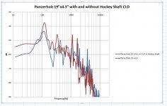
The brown trace is a 19x4.3 inch Panzerholz piece on it's own. It's supported on each end and struck with marbles as close to dead center as possible. The Accelerometer is mounted on the center of the long side.
I cut off a section of a Composite Hockey Stick shaft and filled it with a flexible foam meant for installing windows. Then I stuck it to the Panzerholz with Ductseal. This is the Blue trace.
It seems to have lowered most of the peaks by several db (while shifting a few of them a little higher in frequency).
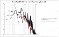
Not an overwhelming success in my view... Above 2khz, the levels seem just a bit higher. I wonder if the characteristics of the Composite Shaft do that. It's shown as the Black trace on the second chart. (Or, maybe I'm seeing another limitation in the test method).
What I wanted to post was the shorter decay times. I may add those later if I solve that xls file problem.
Do you think this combination has a negative effect on Fc?
Hugh
Here's what I tried last night. I wanted to see if something light but reasonably stiff could improve on Panzerholz on it's own. No Hammer yet - still marbles.
The brown trace is a 19x4.3 inch Panzerholz piece on it's own. It's supported on each end and struck with marbles as close to dead center as possible. The Accelerometer is mounted on the center of the long side.
I cut off a section of a Composite Hockey Stick shaft and filled it with a flexible foam meant for installing windows. Then I stuck it to the Panzerholz with Ductseal. This is the Blue trace.
It seems to have lowered most of the peaks by several db (while shifting a few of them a little higher in frequency).
Not an overwhelming success in my view... Above 2khz, the levels seem just a bit higher. I wonder if the characteristics of the Composite Shaft do that. It's shown as the Black trace on the second chart. (Or, maybe I'm seeing another limitation in the test method).
What I wanted to post was the shorter decay times. I may add those later if I solve that xls file problem.
Do you think this combination has a negative effect on Fc?
Hugh
Attachments
the levels (height of peaks) are related to what? Traces look too jumbled to draw any conclusions.
I'm sure you are enjoying your time with the accelerometer, but Panzerholz on its own, is about as good as it gets for obtainable material. By adding more material, I can't see it getting any better. Are you chasing rainbows?
Make a plinth from 'pure' Panzerholz, with a thickness somewhere between 15mm and 25mm, and sit back and enjoy your music.
 panzerholz parameters © cats squirrel
I'm sure you are enjoying your time with the accelerometer, but Panzerholz on its own, is about as good as it gets for obtainable material. By adding more material, I can't see it getting any better. Are you chasing rainbows?
Make a plinth from 'pure' Panzerholz, with a thickness somewhere between 15mm and 25mm, and sit back and enjoy your music.
panzerholz parameters © cats squirrel
Last edited:
By adding more material, I can't see it getting any better. Are you chasing rainbows?
https://flic.kr/p/2jPRtpCpanzerholz parameters © cats squirrel
Bryan,
Yes, it's looking that way. And, yes I am enjoying the Accelerometer and making up these combinations of materials. I'll ty a few more. I'm not counting on any miracles.
Thanks for all your help.
Hugh
Hugh,
Sorry, I just saw this. I've been in the process of moving so haven't checked in lately.
The thinnest of the Tape-Rite VHB replacements is 5336 (Grey) or 5333 (White) at 0.025" (0.64mm). This is the same thickness as 3M 5925.
Sorry, I just saw this. I've been in the process of moving so haven't checked in lately.
The thinnest of the Tape-Rite VHB replacements is 5336 (Grey) or 5333 (White) at 0.025" (0.64mm). This is the same thickness as 3M 5925.
Hi rsritchey,
Do you know off the top which of the tapes you mention would be the thinnest one? I ask because it seems that thinner is more effective for CLD according to some. I tried it with the Green Glue and it seems to be true.
Hugh
The Link is a White Paper, that covers research and the conclusions.
CLD is referenced within the document.
https://earglobal.com/media/9891/understandingdampingtechniques.pdf
CLD is referenced within the document.
https://earglobal.com/media/9891/understandingdampingtechniques.pdf
cats squirrel
I might ask you if you think the idea of placing the tonearm outside the plinth is useful or harmful? Many thanks
sorry for tardy reply, I don't get notifications, either!
My answer is an emphatic YES, separating arm and plinth has got to be a good thing. I found that sound originating from the plinth reaches the stylus by two routes. One is through the plinth/bearing/platter route, the other through the plinth/arm route. And when I tested it, the amount of vibration from each route was about the same.
So having a separate arm pod would help in reducing vibrations from the arm board, down the arm to the stylus. Another advantage is that of mechanical impedance mismatch. If there is a mismatch between two structures, then vibrations will not be transferred quantitatively, so arranging a significant mismatch will reduce transfer of vibrations. As mechanical impedance is proportional to thickness (and surface mass) making the arm board or the board on which it sits thicker (or thinner!) will reduce transfer of vibrations.
HTH
...Diyaudio used to send email notifications. I'm not getting those any more. ...
Post here:
Thread notifier..stopped... no emails
If you're not a true turntable professional trying to DIY your turntable-tonearm setup , YES, you're true, If you're trying to learn some more , then learn from the best and the ones that made the lightest tonearms and most prone to vibration pickup ever made in the industry too:sorry for tardy reply, I don't get notifications, either!
My answer is an emphatic YES, separating arm and plinth has got to be a good thing. I found that sound originating from the plinth reaches the stylus by two routes. One is through the plinth/bearing/platter route, the other through the plinth/arm route. And when I tested it, the amount of vibration from each route was about the same.
So having a separate arm pod would help in reducing vibrations from the arm board, down the arm to the stylus. Another advantage is that of mechanical impedance mismatch. If there is a mismatch between two structures, then vibrations will not be transferred quantitatively, so arranging a significant mismatch will reduce transfer of vibrations. As mechanical impedance is proportional to thickness (and surface mass) making the arm board or the board on which it sits thicker (or thinner!) will reduce transfer of vibrations.
HTH
BeoGram 2202 Record Deck
They also made the best damped platters with their very flat waved shaped platters with most of the weight placed on the plater perimeter. Before diving into ultra expensive heavyweight highendish turntables anyone interested in designing turntables would better dive into B&O world first cause they might miss the most of best turntable design practices.
Attachments
Last edited:
separating arm and plinth has got to be a good thing.
HTH
Do you believe that the base of the tonearm should tend to have identical characteristics to the plinth or perhaps it is preferable that they are intentionally different?
depends on what you want. Don't forget that vibration transfer is a two way street. If one wants to damp the vibrations in the arm, then transfer to a material which has high intrinsic damping would seem a good thing. But, the damping medium would have to be isolated from its support structure, so that vibrations from below won't pass quantitatively into the arm. So matching mechanical impedance of the arm base and arm board would seem a good thing, and isolation of arm board and support would seem to be the way to go.
I don't believe it would be feasible to decide on the plinth thickness based on the requirements of mechanical impedance of the arm base. The arm board needs to be separate from the plinth, so it can be matched in mechanical impedance to the arm base.
HTH
I don't believe it would be feasible to decide on the plinth thickness based on the requirements of mechanical impedance of the arm base. The arm board needs to be separate from the plinth, so it can be matched in mechanical impedance to the arm base.
HTH
Last edited:
"The arm board needs to be separate from the plinth, so it can be matched in mechanical impedance to the arm base."
keeping tonearm and turntable on separate bases, if the tonearm base were anchored to the wall could it give any benefit? Last question, I promise! Anyway many thanks Cats Squirrel!
keeping tonearm and turntable on separate bases, if the tonearm base were anchored to the wall could it give any benefit? Last question, I promise! Anyway many thanks Cats Squirrel!
Last edited:
I've often said that if mass was a benefit, then strapping the turntable to the nearest mountain would do wonders for the sound. Of course, that was very 'tongue in cheek'.
The problem with this scenario is that if things that vibrate (turntable, arm, plinth, support) are isolated, then they must deal with the problems themselves. And of course, they can't unless made of material/s that damp sufficiently. Damping really is the key to this 'Vibration Measuring Machine'.
Ask away, if I can help you get where you want to be.
- Home
- Source & Line
- Analogue Source
- DIY CLD Plinth Design--A measured Approach