I'm at step 17, "Initial Power Up." I'm using a 30v dual rail power supply with the 9.1 kOhm resistor parallel to R17. Before testing the boards, I checked the voltages (+- 30V) and current (0.3A).
For channels A and B, the output voltage is 306 and 315.9 mV, respectively. Are there any issues with this? I assume this was because of the lower voltage PS. Should I be concerned?
I proceeded with testing. The TP-105 voltages for channels A&B were 1.23V and 1.308V, and the TP-106 voltages were 1.286V and 1.312V.
Adjusting R109 resulted in max voltages of 1.337V and 1.336V. This is slightly below the 1.4V—1.45V listed in the instructions. Is this OK?
This is my first SS amp build, so I appreciate the detailed build guide and support on the forum!
What points were tested to get 306mV and 315mV? Assuming this is spk output to ground I.e. DC offset, you should be able to adjust R25 to get this somewhere around 0, no?
TP105 and 106 look okay, although you don’t clarify what transistors you used in 101 and 102. Assuming toshibas
R109 no problem there, your power supply is current limited so this won’t go higher. It’s more about making sure that R109 does actually adjust the bias at all. What was your voltage when you had R109 at max resistance?

Turned my auxiliary circuits design from #3622 into a real life prototype and did some initial hardware tests. After a session with the usual prototype tweaking it now all seems to work. The software still has to be written so I can only test isolated parts at the moment. Below a scope capture while measuring the shut down response of the MOSFET solid state relay, yellow control signal, blue is output. I measured 28 micro seconds, that is way faster then it takes the low pass filter to produce a step response. At the bottom a spice output from the DC detector, green is DC sweep -70V to +70V, blue is the output. Fault condition below -1.3V and above +1.3V DC offset.


Question.
I am about to start troubleshooting the left channel.
As I remember I had connected speakers whilst the amplifier was powered, something happened and I had a measurement of only 2v as a consequence.
What is the best approach to troubleshooting and where to begin? Thank you
Another thing, as I remember I have set bias wrong (way too small, wrong range selection on DMM), this will need to be rectified too, but the most nascent problem is what happened to the board and which component went kaput.
Thanks in advance.
DC Power is supposed to be connected between the rails and ground, not to the output. Voltage is not measured in ohms. Did your short the output back then when you where connecting the speakers? Usually doing so will produce a spark, a sound, and possible a mark on the connecting part.
Are both sides of your GWInstek switched on, and wired as they should? What are the current limiter and output voltage set to? Are the fuse's of the amp still ok?
Are both sides of your GWInstek switched on, and wired as they should? What are the current limiter and output voltage set to? Are the fuse's of the amp still ok?
I've installed the output transistors. All measurements in step 19 were above the minimum threshold. I tested all output transistors for shorts, and none were found. I have removed J103. The 9.1k Ohm resistor remains in parallel to R17.
Step 20E asks to measure the output bias between TP101 & TP102. I put my leads on the board test points (not R111A & R111B). After powering on, I get a reading fluctuating between 0.0 and 0.1 mV. If I move my test leads to R111A & R111B, the reading is similar to what it was in the output transistor installation.
Step 20J asks to turn R109 until a reading of ~40mV is achieved. When I adjust R109, nothing happens. There is no change in the output transistor bias. Any ideas?
Trying to remember how everything works after a hiatus.
V+ to output shows, v- to output shows 1 ohm, should be over 10k
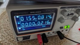
Used bench psu for power up.
Less than a volt for the output bias.
Psu image attached just in case
V+ to output shows ... what?
Anyway V- to output at 1ohm suggests blown (shorted) output (R trace+R emitter+R zobel coil), were rail fuses blown did you replace fuses?
My troubleshooting would then be something like remove all that channels output transistors and go back to step 16 of the build guide.
- Home
- Amplifiers
- Solid State
- DIY Class A/B Amp The "Wolverine" build thread