Thank you Dave and vanofmonds. Please help me understand. Appreciate Nelson or anyone chiming in on this to help me understand what I am or am not seeing. This is my understanding of how the circuit works and per my reading there is a problem Houston.
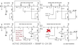
The first and second stage high pass filter sections should be a mirror of each other. There is no jumper in the first stage high pass filter section across the first capacitor. In the second stage high pass filter section when the jumper is in the 6/18 position there is a jumper across the first capacitor. There should not be. It should be identical to the first stage section where the input is going thru the first C then the second C (which equals C/2) and the R of the 10K plus P1 value.
Similarly on the low pass filter section the first stage low pass filter section is a mirror of the second stage low pass filter. There are no jumper positions that would bypass the (10K + P2). This is how it is on the schematic and in the circuit and how it should be per my understanding.
The circuit at it simplest for the high pass filter is the input going into a capacitor and the output being taken between the capacitor with a resistor going to ground. At the frequency when Xc = R is the cutoff frequency. There are four sections and each has to have the same cutoff frequency, if one section is used the slop is -6dB, two -12dB, three -18dB, four -24dB.
For the first stage of the high pass filter there are two C/R networks. The first being the first capacitor (C ) and the R (the 10K resistor and value of P2). The second being the first capacitor ( C) and a second equivalent value capacitor ( C) in series (which is C/2) and the R (the 10K resistor and value of P1). Note that the value of P1 should be twice the value of the P2, see calculator here: http://doublesecretlabs.com/apps/passxo/ The reason is to keep the R/C of each section the same. As R x C = C/2 x 2R; to keep fc the same fc = 1/(2*pi*R*C).
For the low pass section again at its simplest the input going into a resistor and the output being taken between the resistor and a capacitor going to ground. At the frequency when Xc = R is the cutoff frequency. There are four sections and each has to have the same cutoff frequency, if one section is used the slop is -6dB, two -12dB, etc.
For the first stage of the low pass filter there are two R/C networks. The first being the first resistor R (10K + value of P2) and the C value. The second being the value of the first R (10k + value of P2) plus second R (10K + value of P1) and C/2 value. The value has to be C/2 and the equivalent resistor value is doubled to keep each sections R/C values equivalent. As C X R = C/2 X 2R to keep fc the same.
With the jumper across the first capacitor of the second stage, this what I see happening. If you have a high pass filter of say 3.5K Hz and selected C/R values accordingly. In the -6dB position; the cutoff frequency will be 1.75K Hz. If in the -18dB slope position; the first stage section will provide a cutoff of 3.5K Hz at -12dB, which will be summed with the second section of 1.75K Hz at -6dB. If using the -24dB jumper settings, all is good as you will have 3.5KHz at -24dB.
Again, appreciate pointing out what I am not seeing. Not trying to be "that" guy; however, I believe there is an issue and to correct the issue you need to cut the trace between 6/18 and the input of C. Verified that the circuit reflects the schematic, so it not just an issue with the schematic.
Attachments
Last edited:
First, there is no issue with the schematic or the board, it is correct. I think the confusion you are experiencing may be due to not realizing the functions of the jumpers, or the other choices Nelson made in the name of flexibility.
Let's first focus on the high pass path. Now let's consider the circuit if you want a 12db first order high pass. You would set jumper 1 to 6/12. So labeled because it shorts across the entire initial network, thus allowing for only the second network. The second network can only be a 6db (first order) or 12db (second order) high pass.
Now set jumper 2 to 6/18. Doing removes the first rc filter from the path by shorting cap one and disconnecting the r string. So as set jumper 1 limits to 6/12, and jumper 2 sets to 6 db. You are then left with a rc 6db high pass.
Now set jumper 2 to 12/24. So as set, jumper 1 limits to 6/12, and jumper 2 sets to 12 db. Which you can see that there is a 12db network of rc filters.
Basically, the first network can only be a 12 be network, while the second can be 6 or 12 with a switch to make that possible without changing components. So, j1 set to 18/24 and j2 set to 12/24 you get 24 (12 first and 12 db second net). J1 set to 18/24 and j2 set to 6/18, and you get 18 ( 12 first and 6 second net). J1 set to 6/12 and j2 set to 12/24 and you get 12 ( bypassed first and 12 second net). Finally J1 set to 6/12 and J2 set to 6/18 and you get a 6 db first order.
Also C/2 is a different capacitor at half the value of C. e.g., C=0.2u and C/2=0.1u. It has to be a separate physical cap.
So the circuit allows you to try 6, 12, 18, and 24 db crossovers without changing components, only using switches and pots. as far a the low pass, due to choices to make it simpler, the R for the 6db low pass is limited to 20k at its lowest value, as opposed to 10k at lowest value for the other networks.
This is DIY audio after all, and it's a learning experience.
If you feel strongly the trace needs to be cut, go ahead. It won't be the end of the world. The trace-cutting police are not going to show up at your door and arrest you.")
You need to remember also that this is a generic setup. (The filter component values are arbitrary.)
It's up to you as the user to create what you want. An asymmetric crossover....or under(over)-damped filter sections....or differing high/low pass frequencies....or whatever.
Have fun and learn. That's what it's all about.
Dave.
If you feel strongly the trace needs to be cut, go ahead. It won't be the end of the world. The trace-cutting police are not going to show up at your door and arrest you.
You need to remember also that this is a generic setup. (The filter component values are arbitrary.)
It's up to you as the user to create what you want. An asymmetric crossover....or under(over)-damped filter sections....or differing high/low pass frequencies....or whatever.
Have fun and learn. That's what it's all about.
Dave.
Got it on the functions of the jumpers and how they provide selectable slopes by bypassing 1, 2, or 3 stages of RC network. What has been pointed out is with the postion of the second stage high pass filter in the 6/18dB position bypasses the first capacitor. That changes the value of C in the RC network as the two capacitors are no longer in series providing an equivalent capacitance value of the C/2. C/2 is actually selected in low pass circuit, but done cleverly in the HP circuit by putting two capacitors in series to get C/2. Cool beans, nicely done Nelson. It has been pointed out.
Last edited:
Just to have other inputs on the circuit so it all in one place, input impedance, and exact fc values to point out if someone is interested.
With 50K pots, the input Z is 25K in a two channel setup, and 16K if you use a three channel setup. Not too much of an issue unless you are running a tube pre. However, consider using 100K pots so input Z is the more standard 50K input Z. 150K for three channel setup. Rather than a pot I used a switch and fixed resistors values for a total desired resistance and step down resistor values that provide a -1dB step down for each switch position. Providing control of 0 to -6dB in 1dB steps.
To determine my desired fc initially used the calculator here: http://doublesecretlabs.com/apps/passxo/ It is a little hard to see where the line (fc) crosses over the -3dB point. Great to get your ballpark value of C and R. Since this is just an RC network you can get exact resistance values for your specific Fc and C from calculator by using a standard RC calculator as R = 1 / (2 * pi * C * fc). R will the combined value of the 10K resistor and the pot value. Remember to use your R and 2 X R values and C and C/2 values where appropriate for the low pass and high pass calculations. A little tricky as you choose R and 2R for HP and one fixed capacitance value, circuit provides C/2 with two series caps for the HP. Circuit provides 2R in low pass as P1 and P2 are in series. Pretty cool stuff, love this circuit.
This is still not correct, the two caps are never in series, there is two independent poles. One of which gets switched out to leave a standard RC single pole. Equal Rs with C and C/2 is just in the low pass. Equal Cs with R and 2R for high pass.That changes the value of C in the RC network as the two capacitors are no longer in series providing an equivalent capacitance value of the C/2.
Have a look at these two calculators
http://www.calculatoredge.com/electronics/sk high pass.htm
http://www.calculatoredge.com/electronics/sk low pass.htm
You will see on the high pass that the caps are always equal and the ratio is on the resistors


Sincere appreciation for attempting to get me to understand. Honestly, still not getting it. I may be too close, and need to step away and ponder lightly as I seem to be pretty locked in on these R/C paths. Hopefully the aha moment will come and I am not too thick to get it.
OK, I get it now. Thank goodness there are people here (and a lot of other places) who are smarter than I am. I guess that's why one guy designs amplifiers, and this other guy designs patios! I completely missed the need to double resistance for C/2. Elegant, indeed. I promise that if Mr. Pass ever offers a critique of one of my patio designs, I will let him down gently.
Great community here, always ready to help.
Great community here, always ready to help.
I'm going to swap the Q1 J113s for LSK170s bought a while ago at the store (finally getting to this build). I have 3 sets of quad matched B grade. These were from before they split the quads to 2 ranges. Is there any real gain to determining the exact idss of each quad and tweaking the Q2 bias resistor, or would that likely show minimal benefit over the q2 bias resistor in the kit?
Could someone kindly explain, what we are winning using the LSK170s? technically speaking and/or soundwise?
I also have been working on adding film capacitors outside of the PCB, I know many people do it by principle, but anybody can report an improvement?
I've got very nice sound results in my setup, but you know, always looking for an improvement and learning something.
All the best,
Carlos
I also have been working on adding film capacitors outside of the PCB, I know many people do it by principle, but anybody can report an improvement?
I've got very nice sound results in my setup, but you know, always looking for an improvement and learning something.
All the best,
Carlos
I'm trying to put together a DigiKey order and am a bit stumped on the C & C/2 caps. My target crossover point is 650 hz and I have calculated C = 9.231 (10) nF = .010 mF = 10,000 pF and C/2 = 4.615 nF = .0047 mF = 4,700 pF.
I've never ordered from DigiKey before and I'm having a hard time figuring out which capacitors I'm actually supposed to order. I have identified FKP1G021004B00KSSD and FKP1G014704B00KSSD, but don't know for sure that I am correct. And, of course, please let me know if I've made a mistake in my calculations.
Thank you!
- Home
- Amplifiers
- Pass Labs
- DIY biamp 6-24 crossover