Hello, sharing my project... Solid state is an Aleph-J and a Single Ended Triode on the top with a passive section for the horn and the tweter. View attachment 1272524 View attachment 1272523
Cool looking setup with very transparent speaker foots, for that extra transparent sound. 🙂
But i would say that the amp really, really needs free air flow, unless you want to barbecue it, grill all the caps, heat torture the active devices and hard toast the crossover on top to a smoking crisp.
🎺🙂🎸
@davidkou I understand your premise and desire, but you've taken a fork in the road that has a big road-block in it.
FYI, there is a complete analog signal processor solution for the LX521 system which could be modified to accommodate your project. But, it's full of op-amps which I suspect would violate your openness, dynamics, and transparency desires?
Dave.
FYI, there is a complete analog signal processor solution for the LX521 system which could be modified to accommodate your project. But, it's full of op-amps which I suspect would violate your openness, dynamics, and transparency desires?
Dave.
Last edited:
@Davey I tend to avoid op-amps where possible, but am prepared to use them in a limited way if there's no alternative, I can then play around with chip swapping. I found they can sometimes sap some life from the Music.
I doubt that SL's turnkey op-amp LX521 type solution would do it for me (too complex and reliant on too many op-amps?). I've not had chance to hear it.
I'm aiming at a much simpler, mainly B1 follower type solution, perhaps hybridized with a few op-amp sections inserted into channels where absolutely necessary. I also don't mind using some PC based upstream DSP for the room modes and/or global EQ.
Ultimately though, I will forego strict accuracy in the tech specs, but I don't think the end result will be too problematic at all.
Last edited:
The Aleph J is 25w class A. Do you think an inch tall feet between the SS and the AXO is enough , or it should just be totally alone on it's own?Cool looking setup with very transparent speaker foots, for that extra transparent sound. 🙂
But i would say that the amp really, really needs free air flow, unless you want to barbecue it, grill all the caps, heat torture the active devices and hard toast the crossover on top to a smoking crisp.
🎺🙂🎸
Yes, the cristal jars look simple, but it's not only about transparency, they were sealed with the breath of a prima donna opera singer
 , also what I had at hand in the kitchen when I needed to raise the woofers...
Cheers,
Carlos
or it should just be totally alone on it's own?
Since the amp is in the cabinet, I would have it alone.
Error on schematic? This threw me for a while until I figured it out. The schematic provided by Mr. Pass in the 6-24 article linked in the first post does not show the shorting path around P2 and its associated 10k resistor when the 6/18 jumper is selected in the low pass second stage. It appears that the line was started, but never drawn completely, as it is around the capacitor in the high pass section. Not important unless one opts for a 1st or 3rd order crossover, but probably worth revisiting the schematic to correct for posterity.
Otherwise, this entire project is amazingly versatile and provides a unique opportunity to obtain excellent integration between drivers and provide detailed, dynamic, accurate audio not attainable with fixed component values and opamps. I am very grateful for this.
Otherwise, this entire project is amazingly versatile and provides a unique opportunity to obtain excellent integration between drivers and provide detailed, dynamic, accurate audio not attainable with fixed component values and opamps. I am very grateful for this.
@madisonears This was already noted back in Post #926. I believe that is intentional and the schematic is correct.
Dave.
Dave.
Thanks, Davey, for pointing that out. Guess my mind was getting numb after reading 925 posts in this thread. Yes, the board is built according to the schematic, so that aspect is accurate. However, there seems to be an error in design in that the selector pins do not, in fact, provide the indicated results. True, the xover functions when 6/18 is the selected path, but it includes two resistors (a fixed and a variable) that are superfluous and will alter the corner frequency unless accounted for in calculations. Unless this was done to accommodate circuit layout complexity, this seems like a mistake. Changing pcb at this point is impractical, but perhaps there should be an addendum to instructions. I have great respect for Nelson's knowledge and admire his willingness to share it with us, but we are all human and subject to making mistakes. If it's intentional, it should be noted and, possibly, explained. Perhaps 6/18 is a rare selection for xovers and this doesn't affect many builders, but I wonder how many have figured it out for themselves. It took me a while to comprehend.
I plan to remove the extra parts and jumper the open path. This will limit future flexibility, but make the circuit "correct." One could just as easily install parts with negligible values or simply calculate total values including the extra resistors, but if one pot in the signal path is at all detrimental, can two be better?
Again, I really appreciate this design, its implementation, its utility, and its incredible value. After so much struggling with active xovers employing fixed value components and opamps, my speakers have never sounded this good. Thank you to Nelson Pass and the DIY store for providing something I could not have accomplished on my own.
Thought of that, but instead removed pot and superfluous 10k resistor and both sets of selection pins. Installed jumper directly from 18/24 first stage output to the OUTPUT of the first pot in the second stage, thereby eliminating four components: two resistors and the two sets of selection pins. I did not notice a significant difference in signal quality. There were no veils lifted and my wife didn't call out from the kitchen about what I had done to the stereo. There were no veils previously, and I don't currently have a wife.
What I did notice because it was significant, is the output level increased. I had to turn down the volume on the low frequency monoblocks because the lower frequencies were overwhelming the mids and highs. Since I had made no changes to the values of the parts in the circuit (the resulting two resistors equaled what the four resistors were originally, or were very close), I can only assume the direct wiring instead of using the selector pins and the little slide-on connectors makes some kind of difference. I didn't take actual measurements before and after the mod, but it certainly sounded different with considerably louder lows. I don't care to reverse the mod, but it would be interesting if anyone else removes or has removed the three pin selectors and hard wire the two sections together to learn if that makes any difference. I can't figure out what else might be responsible for what I heard.
What I did notice because it was significant, is the output level increased. I had to turn down the volume on the low frequency monoblocks because the lower frequencies were overwhelming the mids and highs. Since I had made no changes to the values of the parts in the circuit (the resulting two resistors equaled what the four resistors were originally, or were very close), I can only assume the direct wiring instead of using the selector pins and the little slide-on connectors makes some kind of difference. I didn't take actual measurements before and after the mod, but it certainly sounded different with considerably louder lows. I don't care to reverse the mod, but it would be interesting if anyone else removes or has removed the three pin selectors and hard wire the two sections together to learn if that makes any difference. I can't figure out what else might be responsible for what I heard.
@madisonears Well, if you didn't take before and after measurements you're flying blind here. I don't understand your approach. ")
Oh well.
Dave.
Oh well.
Dave.
Can you describe your power supply (for the XO)?@corerftech
before I'd build and used the 6-24 xo I played with an old inkel div-23 electronik xo
and noticed that I could'nt feed my poweramps with it's poor output.
So I decided to build the 6-24 xo with following 4 x DIY Front End 2022.
Works great.
cheers
Attila
Thanks
x post to store feedback
Not sure if this is the right place, but the link to the Pass diy 6-24 crossover article is broken on page: https://diyaudiostore.com/collections/crossovers/products/diy-biamp-6-24-crossover
I think it should point to https://www.firstwatt.com/wp-content/uploads/2023/12/art_diy-biamp_6-24_-crossover.pdf
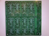
There is an error in the high pass circuit card when you select the 6 or 18dB slopes. If you use 6 or 18dB slopes the fix is to cut the trace between the 6/18 and the C.
Discussion. I looked at the madisonears post about superfluous circuitry in the low pass circuit also discussed in post 926. I am interpreting the circuit the low pass schematic as correct as drawn. Fc = 1/(2 * pi * R * C). When 6 or 18dB the resistance has to double (10K + P2 + 10K + P1) (where P1 = P2) for the C/2 capacitor to have the same fc as the single resistance (10K + P2) and C. There is no issue with the low pass circuitry.
I then looked at the high pass circuitry. The second stage should look identical to the first stage. The schematic shows a trace from the input to the second stage going to the 6/18 jumper (bypasssing first capacitor). I thought this would be just an issue on the schematic and not on the circuit card. Unfortunately, it is on the circuit card (see pic). With the trace being there it provides an incorrect Fc (1/2 of desired value) from what you have in the two RC networks in the first stage and the other RC network in the second stage. One capacitor is bypassed so rather than having two in series which halves the capacitance you have double the desired capacitance. P1 resistance is approximately double of P2 as the capacitors are in series (halved) so both fc will be the same. Sorry to be the bearer of bad news.
Please someone prove me wrong. I have not cut my trace as it is late and would appreciate if someone checked my work.
This is the slickest design; its elegance is in its simplicity. Just love this in my system set up as 3 way xo. Thanks again Nelson!
Attachments
Last edited:
I agree with Davey. You aren't following what the jumpers are doing. The 6/18-12/24 jumper at the start of the second stage will set whether the second stage is a first order high pass (by connecting the input of the stage directly to the second rc network effectively removing the first rc network), or a second order high pass (by allowing connection to the first rc network).
- Home
- Amplifiers
- Pass Labs
- DIY biamp 6-24 crossover